A Simple Voltage Divider Circuit
Here we have a quick repost of a tutorial which I originally developed for the IoST project that I worked on back in 2015/2016. The tutorial details how to make a simple voltage divider circuit that can be used to measure input from physical variable resistance sensors such as flex sensors and pressure sensors.
A variable resistor is one which changes its resistance when interacted with. Using the flex sensor as an example; as we bend the sensor its resistance increases. We can then measure that change using an a micro-controller; such as an Arduino via one of its analog inputs.
In order to do that however; we first need a fixed resistor (not changing) that we can use for providing a comparison. This is called a voltage divider circuit as the supplied voltage is divided between the sensor and the resistor.
How it Works
The analog read on your micro-controller is basically a voltage meter. Arduinos run at 5v , so at 5V (its max) the analog pin would read 1023, and at 0v it would read 0. The amount of the 5V that both the resistor and sensor gets is proportional to their resistance. So if the the sensor and the resistor have the same resistance, the 5V is split evenly (2.5V) to each part. (analog reading of 512)
A Practical Example
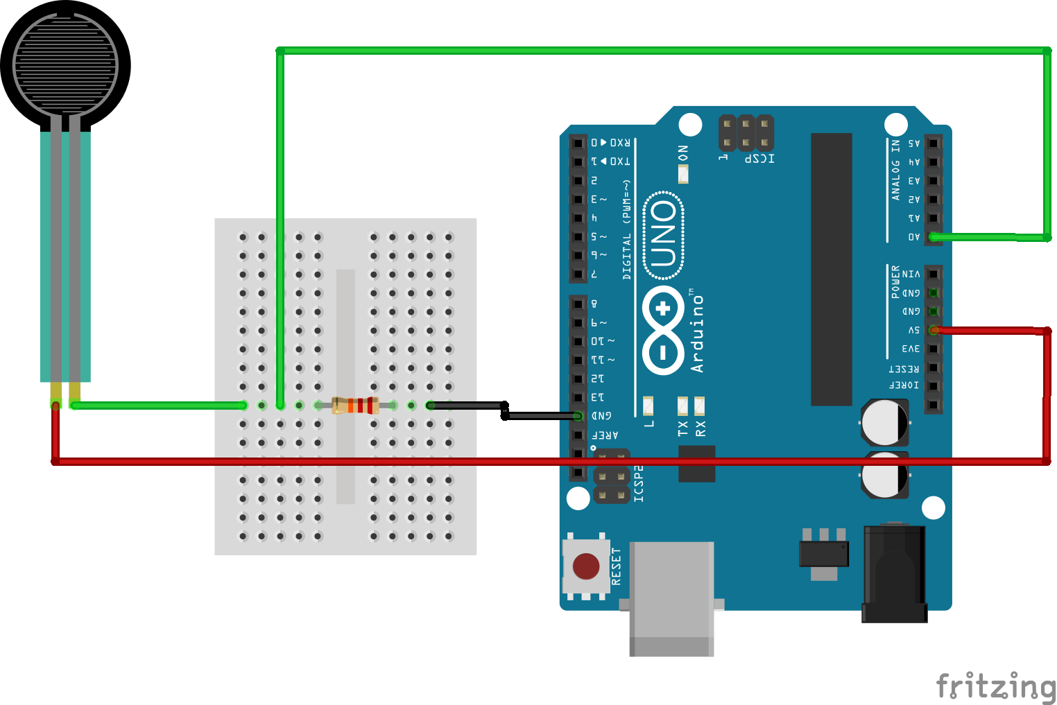
The following is an example of a voltage divider circuit used for a pressure sensor. As you can see the sensor is connected to the Arduino via the pin A0. It is also connected to the 5v supply. The comparison resistor is simply connected to the signal line of the sensor and then to GND. An easy way of looking at it is that the two resistors (one the sensor) are connected in series; whilst the data output is connected between them:
Here is an image of the same circuit however this time physically put together on the breadboard. A few extra wires have been added just to allow for ease of wiring both the 5v and GND lines.
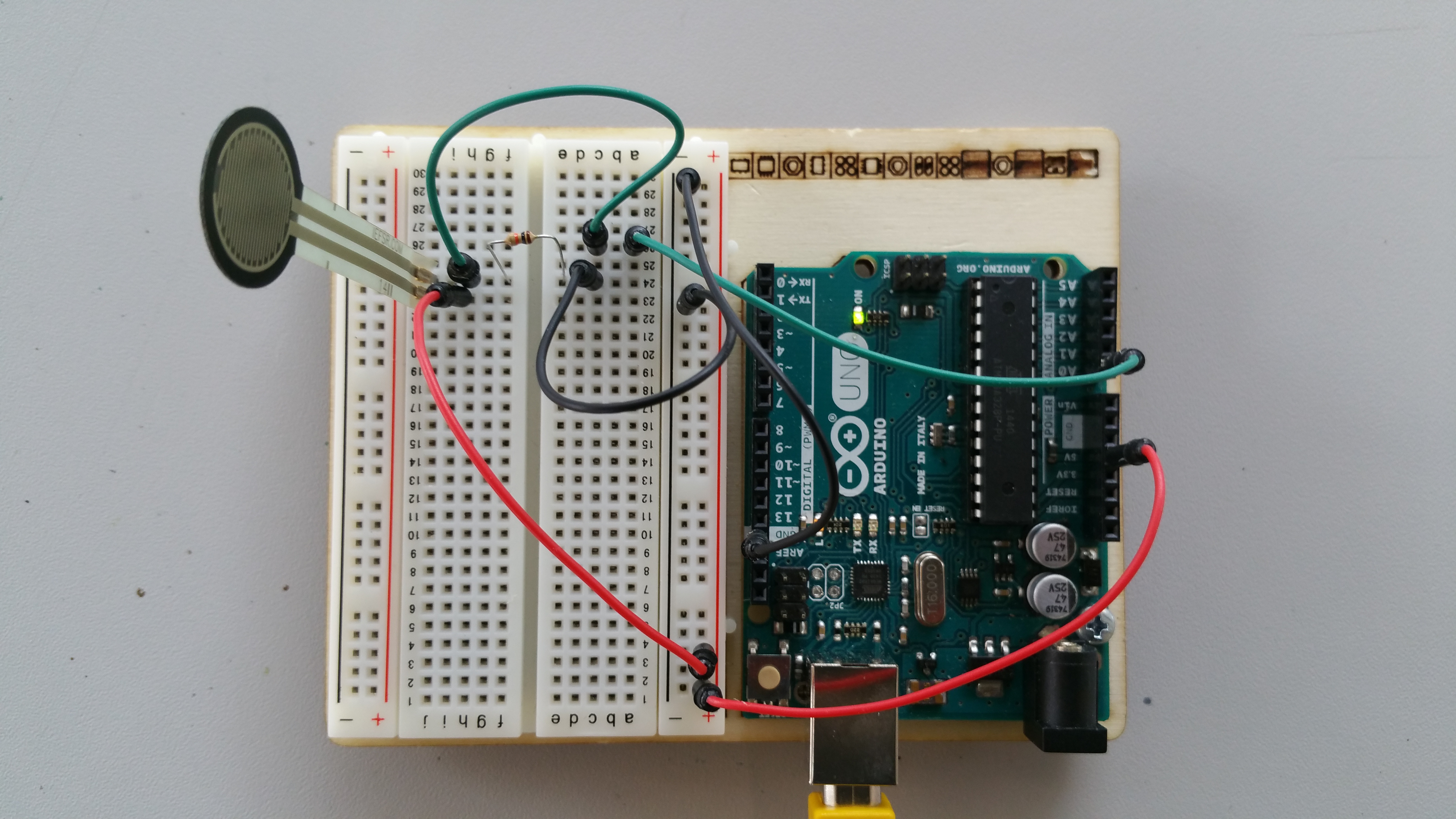
These can be singular wires if you have them long enough.
The Code
The code for this circuit could not be simpler. All we are really doing is reading the value from the A0 pin via an analogRead call. In order to display the data we then make use of the Serial.println command.
A copy of this post published via the IoST Project can be found here.