Basic Differential aka Tank Drive
With the Ratchet hardware build now complete, my developmental focus has turned to the software needed to run him. First up of course has to be getting him to move.
The following post introduces a couple of basic scripts, one in C# (for the desktop) and the other in C (for Ratchet himself). The scripts have been developed to provide Ratchet with capability to calculate the speed and direction values needed for differential drive movement, both on and off the robot.
I have included with the scripts a framework for serial driven robot control built upon both my Simple Serial String Parsing Script and Unity3D Serialport Script so that control is available via serial command and is also compatible with the Unity3D games development platform.
At the heart of both versions of the direct drive scripts you can find a direct conversion of the differential drive JS code found over at goodrobot.com. However I have also included a few amendments such as a filter for NaN values resulting from division by zero. I may over time replace this implementation with a custom Arduino library based on Douglas Taylor’s Diamond Drive method, however it will more than suffice for now.
What is Differential Drive
A Differential Drive system is a method for movement that relies on only two wheels to provide both steering control, and directional movement. As the wheels can move independently from each other (hence differential drive), the speed difference between the left and right determines both the turn and how much to turn.
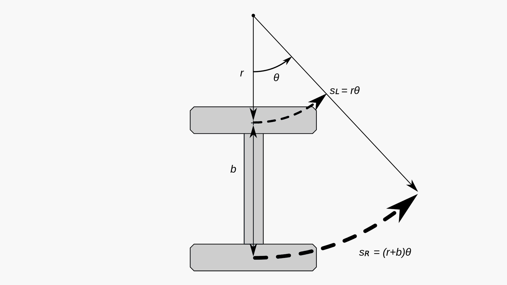
Figure 1: Path of wheels through a turn.
For example, if both the wheels are driven in the same direction and speed, the robot will move in that direction.
If both wheels are turned with equal speed in opposite directions the robot will turn either left or right depending upon the direction of the motors.
Figure 1 shows the path of wheels through a turn (source, wikipedia).
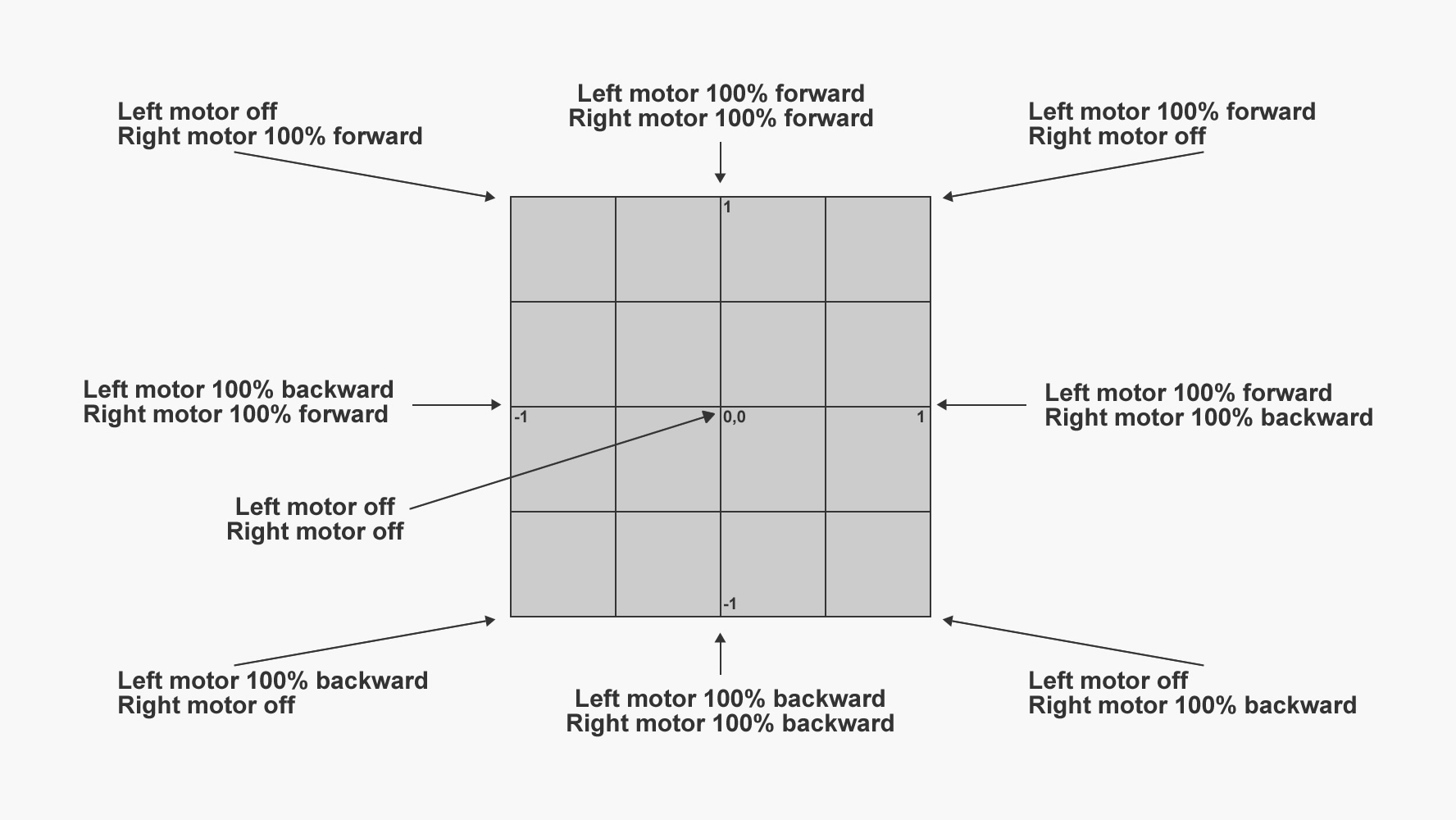
Figure 2: Cartesian Drive Mapping
So what does all this mean in English? Well basically the presented scripts simply map a Cartesian coordinate such as that outputted by a joystick or an equivalent piece of hardware, to the required left and right speed and direction.
Figure 2 shows an image based on one found over at goodrobot.com which shows the input mapping theory in a much easier to understand format than my description.
Ok thats a brief look into the theory, now lets move onto the scripts themselves. As previously stated, this code is a direct conversion of that produced by GoodRobot.com. For more information on how it work’s please check out their relevant post which can be found here.
The C# Script for desktop and or Unity3D
First up we have the C# script. At the heart of this script is a function called CalculateTankDrive. This function takes two float values that correspond to Cartesian x and y. This means that we can call the function and pass it values from hardware such as a mouse and or joystick.
<pre class="brush: csharp; collapse: true; light: false; title: ; toolbar: true; notranslate" title="">

public void CalculateTankDrive(float x, float y)
{
    // first Compute the angle in deg

    // First hypotenuse

    var z = Mathf.Sqrt(x * x + y * y);

    // angle in radians

    var rad = Mathf.Acos(Mathf.Abs(x) / z);

    if (float.IsNaN(rad))
        rad = 0;

    // and in degrees

    var angle = rad * 180 / Mathf.PI;

    // Now angle indicates the measure of turn
    // Along a straight line, with an angle o, the turn co-efficient is same
    // this applies for angles between 0-90, with angle 0 the co-eff is -1
    // with angle 45, the co-efficient is 0 and with angle 90, it is 1

    var tcoeff = -1 + (angle / 90) * 2;
    var turn = tcoeff * Mathf.Abs(Mathf.Abs(y) - Mathf.Abs(x));
    turn = Mathf.Round(turn * 100) / 100;

    // And max of y or x is the movement

    var move = Mathf.Max(Mathf.Abs(y), Mathf.Abs(x));

    // First and third quadrant

    if ((x >= 0 && y >= 0) || (x < 0 && y < 0))
    { rawLeft = move; rawRight = turn; }
    else
    { rawRight = move; rawLeft = turn; }

    // Reverse polarity

    if (y < 0) { rawLeft = 0 - rawLeft; rawRight = 0 - rawRight; }

    RawLeft = rawLeft;
    RawRight = rawRight;

    ValLeft = Remap(rawLeft, MinJoy, MaxJoy, MinValue, MaxValue);
    ValRight = Remap(rawRight, MinJoy, MaxJoy, MinValue, MaxValue);
}
Code 1: The CalculateTankDrive Function
CalculateTankDrive then populates several public properties that can be accessed as required. Code 2 details all of the available properties. You may be wondering why I have structured the properties flat like this. Well this is so that the script be utilized in Unity3D as well as in the traditional WinForm, WPF and XNA usage scenarios.
<pre class="brush: csharp; collapse: true; light: false; title: ; toolbar: true; notranslate" title="">

private float rawLeft;
private float rawRight;

public float MaxJoy = 1;
public float MinJoy = -1;

public float MaxValue = 180;
public float MinValue = 0;

public float RawLeft;
public float RawRight;

public float ValLeft;
public float ValRight;
Code 2: The Available Properties in the C# Script
The important properties are the RawLeft & RawRight properties and also their Value equivalents. The raw properties detail the values as calculated directly from the joystick input, whilst ValLeft & ValRight detail the raw data after it has been mapped onto a custom scale, in turn defined by both the MaxValue & MinValue properties and the MaxJoy & MinJoy properties.
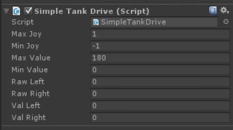
Figure 3: The Tank Script in the Unity Editor
Figure 3 shows how the properties will appear in the Unity3D inspector, once the script has been attached to a game object.
MaxJoy and MinJoy are the current minimum and maximum range of your joysticks output (usually -1 to 1). Whilst MinVal and MaxVal are the range you would like to map to. i.e for full rotation servos 0 to 180 or for generic Arduino usage 0 to 255 etc.
The code used to perform this mapping is simply a C# conversion of the Arduino mapping function as shown in code 3. The function maps a number from one range to another. That is, a value of from1 would get mapped to from2, a value of to1 to to2, values in-between to values in-between, etc.
public static float Remap(this float value, float from1, float to1, float from2, float to2)
{ return (value - from1) / (to1 - from1) * (to2 - from2) + from2; }

// The following is the updated (non static) version of the same function 03.03.2014

public float Remap(float value, float from1, float to1, float from2, float to2)
{ return (value - from1) / (to1 - from1) * (to2 - from2) + from2; }
Code 3: Conversion of the Arduino Map Function to C#
I have included this function as an extension method however you can just as easily drop it in as a static and or additional public function if you wish.
Update 03.03.2014 – After a little more development I have decided to add the mapping code as a public returning float. This code can now be found at the bottom of the SimpleTankDrive class. I have also included the updated code above (code 3) for reference.
It is important to note, that as the CalculateTankDrive script is made available in two forms, both the desktop and robot, we have several methods available to us for control. For example as well as being able to send the values calculated via the CalculateTankDrive function, we could also just send the joystick x, y data to the robot. In this instance the calculation could then be performed on board.
<pre class="brush: csharp; collapse: true; light: false; title: ; toolbar: true; notranslate" title="">

void Update ()
{
    // Get the Cartesian input (joystick/keyboard)

    float x = Input.GetAxis("Horizontal");
    float y = Input.GetAxis("Vertical");

    // If you want to send the raw values to and
    // perform calculation on the robot you can
    // use the following line. JV tells the receiving
    // code that the data is just basic Joysick values.

    // string data = "V," + x + "," + y;

    // Otherwise you have two additional options,
    // the sending of Raw or Value data

    // Use the x,y input to derive the wheel speeds

    CalculateTankDrive(x, y);

    // Use the derived speeds to create a data msg.

    // To send raw data use the following:

    // string data = "R," + RawLeft + "," + RawRight;

    // And to send mapped data:

    string data = "V," + ValLeft + "," + ValRight;

    // Send the data over the SerialPort to the
    // connected robot.

    // First we must check that we have a serial
    // port and that it is open.

    if (unitySerialPort.SerialPort != null && unitySerialPort.SerialPort.IsOpen)
        unitySerialPort.SerialPort.WriteLine(data);
}
Code 4: The Unity3D Update Function
This duplication also covers us for scenarios such as we want the robot to perform autonomously. In this instance the x and y values could either be derived by different means such as sensor driven input or even as a blend of both sensor and human input.
The next block of code (4) shows each potential desktop serial output encased in an Unity3D behavior Update() function. As always the code is fully commented so that you can hopefully follow along etc.
The C script for Arduino and drive calculation on the robot
So far we have focused on utilizing a C# application to calculate the required direction and speed values, however as stated we can also do this on the robot end if we wish, which brings us nicely onto the C version of the code. As indicated the C scripts are pretty much an exact duplication of the C# ones. The only real difference is that it has been wrapped to fit in with the Arduino way of doing things. The following code block (5) shows the Arduino C version of the CalculateTankDrive function.
<pre class="brush: csharp; collapse: true; light: false; title: ; toolbar: true; notranslate" title="">

void CalculateTankDrive(float x, float y)
 {
   // first Compute the angle in deg
   // First hypotenuse
   float z = sqrt(x * x + y * y);

   // angle in radians
   float rad = acos(abs(x) / z);

   // Cataer for NaN values
   if(isnan(rad) == true){ rad=0; }

   // and in degrees
   float angle = rad * 180 / PI;

   // Now angle indicates the measure of turn
   // Along a straight line, with an angle o, the turn co-efficient is same
   // this applies for angles between 0-90, with angle 0 the co-eff is -1
   // with angle 45, the co-efficient is 0 and with angle 90, it is 1

   float tcoeff = -1 + (angle / 90) * 2;
   float turn = tcoeff * abs(abs(y) - abs(x));
   turn = round(turn * 100) / 100;

   // And max of y or x is the movement
   float mov = max(abs(y), abs(x));

   // First and third quadrant
   if ((x >= 0 && y >= 0) || (x < 0 && y < 0))
   { rawLeft = mov; rawRight = turn; }
   else
   { rawRight = mov; rawLeft = turn; }

   // Reverse polarity
   if (y < 0){ rawLeft = 0 - rawLeft; rawRight = 0 - rawRight; }

   // Update the values
   RawLeft = rawLeft;
   RawRight = rawRight;

   // Map the values onto the defined rang
   ValLeft = map(rawLeft, MinJoy, MaxJoy, MinValue, MaxValue);
   ValRight = map(rawRight, MinJoy, MaxJoy, MinValue, MaxValue);

   // Cater for inverse of direction if needed
   if(invXL){ RawLeft *= -1; ValLeft = MaxValue - ValLeft; }
   if(invXR){ RawRight *= -1; ValRight = MaxValue - ValRight}
 }
Code 5: The Arduino (C) CalculateTankDrive function
As you can see it is almost identical to its C# counterpart. There is however an additional step right at the bottom that caters for the orientation of the motors (code 6). As one motor is mounted on the left and the other on the right, one of them can be seen as being upside down. This means that the control of the motor needs inverting i.e. forwards becomes backwards etc.
// Cater for inverse of direction if needed
if(invXL){ rawLeft *= -1; ValLeft = MaxValue - ValLeft; }
if(invXR){ rawRight *= -1; ValRight = MaxValue - ValRight}
Code 6: The Work in progress inversion code
This is simply done via setting a boolean value to true for the motor that requires inversion. Then when the CalculateTankDrive function is called if the bool is set to true inversion is performed. Please note that I have performed the inversion after the calculation of all the values has completed. This is so that I can treat each type (Raw / Value) separately, however I’m still undecided about this, and may amend in the future.
In addition to the CalculateTankDrive function, there are three additional functions within the Arduino script that can be used to deal with the incoming drive data. Each of these functions is essentially the counterpart of the highlighted output methods found within the Unity3D behaviours Update() function (code 4) as shown below:
- CalculateTankJoyDrive == string data = “J,” + x + “,” + y;
- ApplyTankDriveRawValue == string data = “R,” + RawLeft + “,” + RawRight;
- ApplyTankDriveMapValue == string data = “V,” + ValLeft + “,” + ValRight;
To make use of the functions all you need to do is expand the data count == 3 case statement within the ParseSerialData() method (as found within my Simple Serial String Parsing tutorial). The following code block (7) shows each of the available serial input scenarios. I have left the FunctionA1 example from the original tutorial in there just to aid with bearing etc.
// If the data has three values then..
if(count == 3)
{
  // Define value 1 as a function identifier
  char *func = inParse[0];
  // Define value 2 as a property value
  char *prop = inParse[1];
  // Define value 3 as a period
  char *prod = inParse[2];

  // Call the relevant identified function
  switch(*func)
  {
    case 'A': FunctionA1(prop, prod); break;

    case 'J': CalculateTankJoyDrive(prop, prod); break;
    case 'R': ApplyTankDriveRawValue(prop, prod); break;
    case 'V': ApplyTankDriveMapValue(prop, prod); break;
  }
}
Code 7: ParseSerialData() modifications
Basically, all this switch does is call a function dependent upon the assigned identifiers “J”, “R” or “V”. It then passes the two properties prop = left and prod = right to the function in order for the relevant drive calculation to be executed.
The CalculateTankJoyDrive function is called via the “J” identifier. This function is called when you want to perform the aforementioned tank drive calculation on board the robot. In this instance the left and right values are passed to the CalculateTankDrive function as floats (thanks to the atof conversion) and the resulting values are then applied to the servos.
void CalculateTankJoyDrive(char *prop, char *prod)
{
  // Convert property to float
  float x = atof(prop);
  // Convert property to float
  float y = atof(prod);

  // Use the raw joystick values to calculate the
  // track speeds and directions
  CalculateTankDrive(x, y);

   // Apply the values to the servos
   LeftTrack.write(ValLeft);
   RightTrack.write(ValRight);
}
Code 8: The CalculateTankJoyDrive function
The ApplyTankDriveRawValue function is called via the “R” identifier. In all honesty I haven’t made use of this function yet, however its there just in case and I’m sure I’ll make use of it at some stage 😉
void ApplyTankDriveRawValue(char *prop, char *prod)
{
   // Not yet implemented, but maybe someday!
}
Code 9: ApplyTankDriveRawValue function
The ApplyTankDriveMapValue function is called via the “V” identifier. This function applies the speed and directional values as calculated via the Unity desktop application.
void ApplyTankDriveMapValue(char *prop, char *prod)
{
  // Convert property to int
  int lDrive = atoi(prop);
  // Convert property to int
  int rDrive = atoi(prod);

  // Set ValLeft to the received left value
  rawLeft = lDrive;
  // Set ValRight to the received right value
  rawRight = rDrive;

  // Cater for inverse of direction if needed
  if(invXL){ rawLeft = MaxValue - rawLeft; }
  if(invXR){ rawRight = MaxValue - rawRight; }

  // Set the mapped values to that of the
  // modified raw left and right values.
  ValLeft = rawLeft;
  ValRight = rawRight;

  // Apply the received left value
  LeftTrack.write(ValLeft);
  // Apply the received right value
  RightTrack.write(ValRight);
}
Code 10: The ApplyTankDriveMapValue function
Please note that in this function the inversion code is once again included. This time however, it is only applied to both the ValLeft and ValRight properties as we don’t need to worry about the raw ones. In this instance the left and right values are inverted if necessary and then directly applied to the servos.
Using the Code & Prefabs
As with the prefabs included with the UnitySerialPort code all you need to do in order to use the port is drop the prefab into the scene and set the properties accordingly.
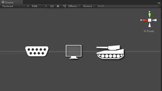
Figure 4: The prefab gizmo icons
This time around I have set the prefab up to appear with a nice tank gizmo when viewed in the scene view (see figure 4).
As with the other prefab’s (see my Unity3D Serialport Script post) it simply consists of an empty gameObject with the featured script attached, and to access the settings as shown in figure 3 all you need to do is click on the gizmo.
And again as with those prefabs there again few Unity3D based gotchas. Firstly you of course need to have a setup copy of the Serialport prefab in your scene. Also in order to be able to utilize the SerialPort functionality of .net you will need to ensure that your Unity project is also set to full .net 2.0 compatibility rather than the standard subset.
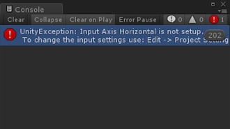
Figure 5: Horizontal input button error
Finally you will also need to ensure that you have set up the required Input axis and button definitions Horizontal and Vertical. These usually should be included by default, however if not you will get an error similar to that as shown in figure 5. That’s it, with these steps, you should be good to go.
A completed version of both scripts is available for download here. Finally I have included is a quick video (below) showing the working code in action.
Video 1: The working code in action
Next time around I will be focusing on getting the headlights up and running. For more information, intermediate updates and if you have any questions, please check out my facebook page.