Building a Calibrated Tilt Compensated Compass with the LSM303
The LSM303 Breakout is a nice little compass module that consists of a triple axis accelerometer and a triple axis magnetometer. When used together this combination of sensors allows the LSM303 to perform 6D orientation detection and provide all the data needed to calculate a tilt-compensated heading.
This post introduces an Arduino sketch that allows both calibration of the LSM303 and the saving of calibration data to the arduino’s EEPROM. This data can then be recalled to configure the LSM303 for use at a later date.
In contrast to my usual postings of this type, rather than giving a step by step breakdown of the whole sketch I will instead pinpoint it’s key features. Those that want to know how things work can grab the sketch from here and follow along whilst those that just want to use it can just grab it and do so.
Hey I’m trying something new, lets just see how it goes 🙂
As always the code is fully commented and it will be hopefully easy for you to understand what’s going on etc.. Please be aware however, that in order to use the code you will first also need to download the Pololu library.
Wiring
The following is a diagram of the circuit produced in Fritzing. I have also provided the Fritzing files for download here.
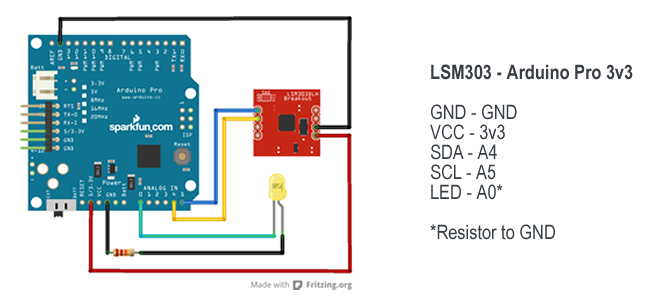
In addition to the sketch, the zip also contains each of the three renderings for breadboard, pcb and circuit diagram just in case for those who don’t want to utilise the Fritzing software.
Outline of the Sketch
The sketch is built upon the Arduino library provided by Pololu for their range of LSM303 breakouts. Despite being developed for the Pololu range, the code works just as well for those developed by Sparkfun. The sketch also utilises the serial communication method as described in my Simple Serial String Parsing tutorial, to switch between both calibration and playback (orientation) modes.
The sketch can be broken down into 4 main sections.
- Using serial communication for control
- Reading and writing to and from the EEPROM
- Obtaining a heading from the LSM303
- Calibrating the LSM303
Using serial communication for control
As with my previous example Simple Serial String Parsing this sketch utilises the Arduino’s serialEvent() to inform of the receiving of data over serial. Once a new line ‘n’ is detected a property is set to indicate that a full line of data has been received.
For this sketch this is used to toggle the code between running in either calibration or playback mode. This functionality is handled via the InputCheck() function and the following lines of code:
// Update the calibration mode
CalibrationMode = !CalibrationMode;
In effect all that’s going on here is toggling of the CalibrationMode property. This property is then used to tell the loop() to call either the code for calibration or playback. The change of CalibrationMode also acts to trigger both the clearing and saving of data.
When calibrationMode is set to false, saving is handled via the following:
// Set calibration to calibrated
configuration.Calibrated = true;
// Save data to the EEPROM
EEPROM_writeAnything(0, configuration);
When CalibrationMode is set to true, clearing is handled via:
// write a 0 to all 512 bytes of the EEPROM
for (int i = 0; i < 512; i++) { EEPROM.write(i, 0); }
Clearing is utilises the default functionality of the Arduino EEPROM library. In effect all we are doing here is setting each register to 0. This is great for this task, however when we want to handle data that doesn’t fall within the default 0-255 range we need another approach, which nicely brings us on to reading and writing data to the EEPROM via EEPROMAnything.h.
Reading and Writing to and from the EEPROM
Up until version 0013 of Adduino, the only way to read and write the Arduinos built-in EEPROM memory was through functions that supported only one byte of data at a time. This in itself is fine for saving a number from 0-255. When saving of a larger “long” number is needed however the method falls down. Luckily Arduino now provide a solution for this as documented here and as documented below:
#include
#include   // for type definitions

template  int EEPROM_writeAnything(int ee, const T& value)
{
    const byte* p = (const byte*)(const void*)&value;
    unsigned int i;
    for (i = 0; i < sizeof(value); i++)
          EEPROM.write(ee++, *p++);
    return i;
}

template  int EEPROM_readAnything(int ee, T& value)
{
    byte* p = (byte*)(void*)&value;
    unsigned int i;
    for (i = 0; i < sizeof(value); i++)
          *p++ = EEPROM.read(ee++);
    return i;
}
This code needs to be added to a new tab within your Arduino sketch and the saved as EEPROMAnything.h. Once this has been done in order to include the code you will need to add the following to the top of your main sketch:
// Arduino EEPROM
#include
// Custom code by Arduino that enables the saving of long data
#include "EEPROMAnything.h"
The next section of code (which can be found at the top of the sketch) defines a struct that is used to store the calibration data. The struct contains both minimum and maximum values for X, Y and Z. Additionally there is also a Boolean that is utilised to tell the system whether it is in either playback or calibration mode:
// Define a struct to store data to
struct config_t
{
  int E_min_X;
  int E_min_Y;
  int E_min_Z;
  int E_max_X;
  int E_max_Y;
  int E_max_Z;
  boolean Calibrated;
}configuration;
Once implemented the data can be written to or retrieved via the following example syntax:
// Write to the E_min_X struct property
configuration.E_min_X = Value;
// Read from the E_min_X struct property
Value = configuration.E_min_X;
So by putting this all together, all we need to do to read and write the EEPROM is utilise the following calls:
// Read in the data from the EEPROM
EEPROM_readAnything(0, configuration);

// Save data to the EEPROM
EEPROM_writeAnything(0, configuration);
Initialisation of the LSM303
In order to use the Pololu library we need to include it and reference it in our sketch. This is achieved via the following lines of code which can be found at the top of the sketch.
// Wire library for I2C
#include
// LSM303 library by Pololu
#include

// Define the compass
LSM303 compass;
// Set min and max variables for calibration
LSM303::vector running_min = {2047, 2047, 2047}, running_max = {-2048, -2048, -2048};
As you can see from this code the LSM303 is a I2C device which means we also need to include the Arduinos wire library for communication. Once both libraries are included reference is made to the compass and also a vector (included with the Pololu library) for defining calibration data (more on this later).
The Setup Function
As with all Arduino sketch’s the setup() function initialises the system and sets things going. Fist off the sketch defines the led pin used for detailing calibration progress (see calibration) to an output. Next it reads in saved data from the EEPROM and stores it to the configuration struct. Once done the serial connection is then initialised and a call is made that outputs the saved data via serial just in case you want to check it etc. I have included a long pause here so that there is enough time to read the data. Finally the function initialises the wire connection used to communicate with the compass and sets it going.
// Set up the system
void setup()
{
  // Define the LED as an output.
  pinMode(LED, OUTPUT);

  // Load stored data from the EEPROM if not
  // showing saved data (call contained within)
  // EEPROM_readAnything(0, configuration);

  // Initialise the serial port
  Serial.begin(9600);

  // Load and show data via serial.
  ShowSavedData();
  // Pause so that data can be read.
  delay(5000);

  // Initiate the Wire library and join the I2C bus as
  // a master or slave
  Wire.begin();
  // Initialise the compass
  compass.init();
  compass.enableDefault();

  // Calibration values. Use the Calibrate example program
  // to get the values for your compass.

  // Minimum values
  compass.m_min.x = configuration.E_min_X;
  compass.m_min.y = configuration.E_min_Y;
  compass.m_min.z = configuration.E_min_Z;
  // Maximum values
  compass.m_max.x = configuration.E_max_X;
  compass.m_max.y = configuration.E_max_Y;
  compass.m_max.z = configuration.E_max_Z;

  // Get the calibration mode
  CalibrationMode = configuration.Calibrated;
}
The only other thing going on here is the assigning of the minimum and maximum values used for calibration and the setting of the system to either calibration or playback mode.
The Calibration Loop
The calibration loop is based on the example provided with the Pololu library, however with a few modifications. Foremost is the addition of code to allow the saving of the calibration data to the configuration struct.
  // Update the configuration store ready for
  // saving data to the EEPROM

  // Update the minimum values
  configuration.E_min_X = running_min.x;
  configuration.E_min_Y = running_min.y;
  configuration.E_min_Z = running_min.z;

  // Update the maximum values
  configuration.E_max_X = running_max.x;
  configuration.E_max_Y = running_max.y;
  configuration.E_max_Z = running_max.z;
Secondly is the inclusion of code that lights a led to show that the values are still updating. All that happens here is that if the new values are either lower or larger than the existing min and max values then the led will light. If they are not then the led remains off. This is a simple way to let you check if the system is still calibrating without need for a visible serial connection.
  // Turn off the led
  digitalWrite(LED, LOW);

  // Turn LED back on if we have any change
  // in the minimum values.
  if(running_min.x != configuration.E_min_X || running_min.y != configuration.E_min_Y || running_min.z != configuration.E_min_Z)
  { digitalWrite(LED, HIGH); }

  // Turn LED back on if we have any change
  // in the maximum values.
  if(running_max.x != configuration.E_max_X || running_max.y != configuration.E_max_Y || running_max.z != configuration.E_max_Z)
  { digitalWrite(LED, HIGH); }
The minimum and maximum values are simply obtained using the Arduino min() and max() functions following a read from the compass.
// Read data from the compass
   compass.read();

  // Update the minimum values
  running_min.x = min(running_min.x, compass.m.x);
  running_min.y = min(running_min.y, compass.m.y);
  running_min.z = min(running_min.z, compass.m.z);

  // Update the maximum values
  running_max.x = max(running_max.x, compass.m.x);
  running_max.y = max(running_max.y, compass.m.y);
  running_max.z = max(running_max.z, compass.m.z);
The Playback Loop
The playback loop is simple really. All that’s going on here is the reading of the compass and then the output of the read data via serial. I have also included a delay to make things easer to read in the serial monitor.
// Loop used for playback
void PlaybackLoop()
{
  // Read data from the compass
  compass.read();
  // Get the heading
  int heading = compass.heading((LSM303::vector){0,-1,0});
  // Output the heading
  Serial.println(heading);
  // Pause a little to make things easyer to read.
  delay(100);
}
As previously stated in order to toggle the code between running in either calibration or playback mode all you have to do is send a “n” command via the serial monitor.
Output Calibration Data to Serial
The final part of the sketch that I will introduce you to is the function used to output the saved data. This part of the sketch is self explanatory and all thats going on here is the output of the data via lots of Serial.print() calls.
// Read data from EEPROM and print to serial
void ShowSavedData()
{
  // Print a seperation line for easy reading
  Serial.println("******************************");
  // Read in the data from the EEPROM
  EEPROM_readAnything(0, configuration);
  // Pause a little just in case
  delay(500);
  // Output Min X via serial
  Serial.print("EEPROM_Min_X: ");
  Serial.print(configuration.E_min_X);
  Serial.println();
  // Output Min Y via serial
  Serial.print("EEPROM_Min_Y: ");
  Serial.print(configuration.E_min_Y);
  Serial.println();
  // Output Min Z via serial
  Serial.print("EEPROM_Min_Z: ");
  Serial.print(configuration.E_min_Z);
  Serial.println();
  // Output Max X via serial
  Serial.print("EEPROM_Max_X: ");
  Serial.print(configuration.E_max_X);
  Serial.println();
  // Output Max Y via serial
  Serial.print("EEPROM_Max_Y: ");
  Serial.print(configuration.E_max_Y);
  Serial.println();
  // Output Max Z via serial
  Serial.print("EEPROM_Max_Z: ");
  Serial.print(configuration.E_max_Z);
  Serial.println();
  // Output Calibration mode via serial
  Serial.print("Calibrated: ");
  Serial.print(configuration.Calibrated);
  Serial.println();
  // Print a seperation line for easy reading
  Serial.println("******************************");
}
Thats all there is to it really and I hope that you find the code of use. For more works in process and additional developments don’t to forget to check out and my facebook page.