Interfacing a PSP or DS Touch Screen with Arduino
The following post demonstrates via an Arduino sketch the interface of either a PSP or DS Touch Screen with an Arduino Pro and/or Pro Mini.
The PSP and DS touch screens are both 4 wire analog resistive touch screen’s. This means by touching the screen at one point, a resistance between each edge is formed for both the x and y axises. As you move your finger across the screen the resistance changes between opposing sides of each axis.
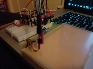
Fig 1: PSP Screen & Arduino Pro Mini
By applying a voltage across each axis, a changing resistance results in a changing voltage. By way of result, simple Analog Digital Conversion (ADC) via four of the Arduino’s analog inputs can be used to find x and y positions. The four pins connected to the screen control 4 buss bars located around the screens edge. In order to read either an x or a y position, two opposing bars need to be powered and a third orthogonal bar is used to measure the divided voltage.
The components used can be sourced as follows:
Both variants of the hardware utilise the same code and both connectors break out to the same connections. The only artifact that you will have to tweak in each case is the Offsets which are screen and usage dependant. These can be found within the main loop.
// Set our pin id's
int y1 = A0;
int x2 = A1;
int y2 = A2;
int x1 = A3;

void setup()
{
// Period to allow for boot up
delay(6000);
// Initialise the serial port
Serial.begin(9600);
// Here we go...
Serial.println("Ready");
}

void loop()
{
// Get our X value
int x = readX();

// Get our Y value
int y = readY();

// Define our offsets (Screen dependant)
int Offset_X = 180;
int Offset_Y = 130;

if(x < 1000 & y < 1000){
Serial.print("x: ");
Serial.print(y-Offset_Y);
Serial.print(",y: ");
Serial.println(x-Offset_X);
}

// Slow things down for readability
delay(100);

}

int readX()
{
// Define the input lines
pinMode(y1, INPUT);
pinMode(x2, OUTPUT);
pinMode(y2, INPUT);
pinMode(x1, OUTPUT);

// Set the input lines
digitalWrite(x2, LOW);
digitalWrite(x1, HIGH);

// Dause to allow lines to power up
delay(5);

// Return reading
return analogRead(y1);
}

int readY()
{
// Define the input lines
pinMode(y1, OUTPUT);
pinMode(x2, INPUT);
pinMode(y2, OUTPUT);
pinMode(x1, INPUT);

// Set the input lines
digitalWrite(y1, LOW);
digitalWrite(y2, HIGH);

// Delay to allow lines to power up
delay(5);

// Return reading
return analogRead(x2);
}
That’s it, I hope that the code is self explanatory, however if you would like some more information as to how the system works check out the How Does it Work? data-sheet provided by Sparkfun here. If your still not satisfied, then sparkfun also provide a Touch Screen tutorial here, on which this code is based.
