Playing with the ArduIMU+ V3
The ArduIMU V3 is an Inertial Measure Unit (IMU) plus an Arduino compatible processor that can run Attitude Heading Reference System (AHRS) code much like the Sparkfun 9DOF AHRS board.
The hardware consists of a 3 axis accelerometer and three gyro sensors, dual power regulator (3.3v and 5v), GPS port, an Atmega328@16mhz and a lot of status LED’s. The best thing about it is unlike the Sparkfun board, this one has additional analog and digital pins so that you can add additional sensors and inputs.
Out the box I already had a plan for what I’m going to use this for so I opted to mount a full aray of header pins. The board itself comes with a six pin angled strip for the communication pins, so I have added standard male headers. This means that whilst the project is in development the board can also be breadboard mounted
Getting up and running
The ArduIMU+ comes with some basic test firmware loaded at the factory, but to get it fully functional you need to load the latest AHRS firmware from 3DR. Before you do this however (especially if your soldering is like mine) run the code via the Arduino serial terminal to ensure the board works ok.
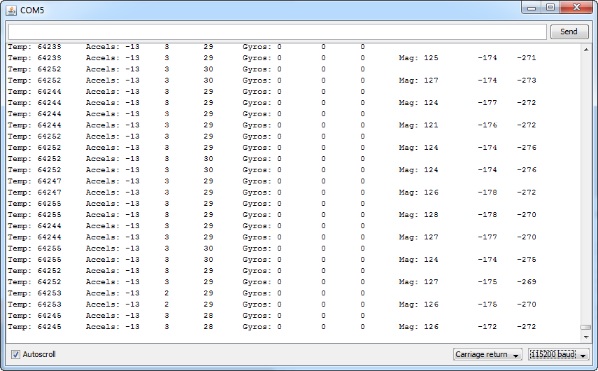
Fig 1: Basic firmware output
If all works ok you should receive the data as shown above. Please note that the gyro’s are reading zero as there is no movement of the board.
Updating the firmware
The Wiki states that you first need to download the latest ArduIMU software. All good so far. It then states that within the .zip will be two folders: “arduimu” and “libraries”. This is wrong, there is in fact only the libraries folder? and another folder that contains a demo app. Also the file location info is just as bad and is of no real help with the install, but not to worry. All you need to do is update Arduino to version 1.0.5 and copy over the libraries folder contained within the .zip to the Documents > Arduino > libraries folder. Once this was done I then had to cut the Arduimu folder from within libraries and move it up to the main directory Documents > Arduino.
Next open up the ArduIMU code within the Arduino IDE via the Sketchbook > ArduIMU. This will open all the tabs required. You can then make any configuration changes needed in the first tab of the code. If you just want to try out the IMU with the desktop demo programs also provided by the Wiki, make sure the following configuration options are set as shown below:
//This will print the analog raw data
#define PRINT_ANALOGS 1

//This will print the Euler angles Roll, Pitch and Yaw
#define PRINT_EULER 1

//This will print GPS data
#define PRINT_GPS 1

//This will print binary message and suppress ASCII messages (above)
#define PRINT_BINARY 0
Code 1: Configuration options
The Wiki states that You should also select a GPS module and defines uBlox as the recommended default. More Information on this can be found via the official wiki page. This can be done via the following line:
// GPS Options: 1 - NMEA,  2 - EM406,  3 - Ublox, 4 - MediaTek
#define GPS_PROTOCOL 3
Code 2: Setting the GPS
Once you are done connect the board to your computer via a FTDI cable/board (I used a 3v3 FTDI USB as shown in first image) via the six angled connector pins. Then simply in good old arduino fashion upload the code to the board. The board settings I used for this are as follows: Arduino Duemilanove w/ Atmega328. If you are having problems DiyDrones provide a great sheet of debug tips here.
Testing it out
In addition to the firmware the DiyDrones community also provide a couple of test applications. The one I opted for was the ArduIMU Test app developed by DiyDrones member, HappyKillmore.
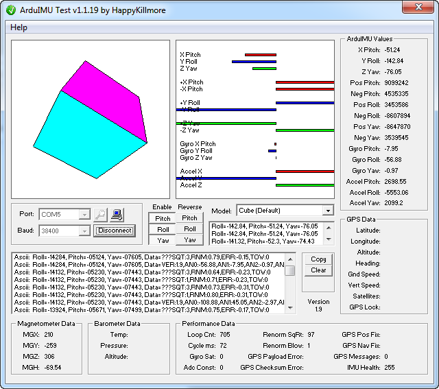
Fig 2: The HappyKillmore test application
Next time out I will be showing you how to extend the code and add additional sensors and inputs. For more works in process and additional developments please check out and like my facebook page here.