Project Leonard - Y Carriage Build
Well some more of the parts for the Project Leonard build arrived today, more specifically the RAMPS electronics. Inspired by this I decided to allocate an hour this evening to a little more of the build. I started by tightening and squaring off the frame. This step takes some time and would be nearly impossible without the aid of spacing jigs (fashioned out of some spare lengths of wood).
With this achieved (maybe a little to tight in places) I then moved onto assembling the Y Carriage. This like all of the build so far was a fairly easy process that consisted of adding the two running bars and attaching the MDF base plate (via gluing to 4 slide on bushings). With this achieved and a little adjustment to ensure that the bed runs the length of the bars smoothly, I also decided to attach the Y stepper motor.
This is done by bolting the motor onto the provided mount, via use of three 3mm bolts (and washers). A little tweaking was also applied to ensure that the cog lines up with the pulley guides. An additional length of wood was used to ensure that the pulleys line up.

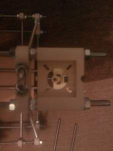
Fig 1: Hole as seen through Z motor mount
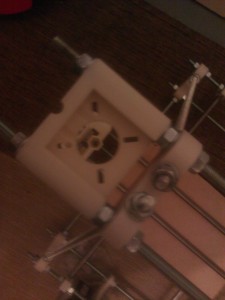
Next, inspired by my successes so far, I decided to start on the X Carriage. As I suspected last time, I did need to drill out holes for the bar mounts. The model print had (as feared) filled both of the 8mm bar to nut holes where the springs are to be situated to help prevent backlash on the Z Axis. You can see an example of the holes added in the photos showing one through a Z motor mount.

Fig 2: Another view of the hole
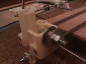
Further inspection of the plastics also identified a similar issue with the 8mm hole within the body of the extruder motor mount, so whilst I had the bit in the drill I also decided to rectify the extruder mount at the same time. With the plastics rectified I moved onto starting to put the X Carriage together. This commenced via inserting eight 3mm nuts into the provided mounts and adding the two 8mm * 420mm bars these are then held in place via 8mm * 10mm bolts (hand tight only). The design of the carriage draws the bars parallel (great design).

Fig 3: The X carriage with bars
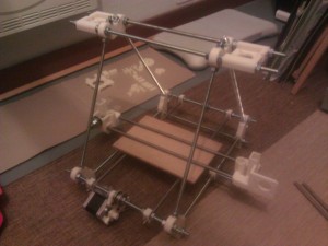
Once completed, attention then moved to the addition of the pulley bearing. This is simply done via threading a couple of washers, fender washers and bearing in the familiar style as utilised via the Y Carriage and as shown in the above image. The following image shows the current state of play:

Fig 4: The current state of play
I decided to stop here for today and will continue from here next time out, when hopefully ill also get chance to check out the electronics.