Ratchet & Clank - Power Harness
Today my attention turned towards a means of providing power for my servo based 3D printed robots, Ratchet & Clank. In order to achieve this I first off defined a list of requirements that any potential solution must fulfil:
- Separate power sources for both the servos and Arduino.
- Can be turned on via a single switch.
- Can power at least six servos.
Luckily the circuit turned out to be dead easy. All I needed to do was tie together both of the ground wires coming from the battery and then wire them to the switch. The switch then provides the ground source for to two male servo plugs. Each plug is also connected to one of each of the positive lines.
As a picture is worth a thousand words check out the following image.
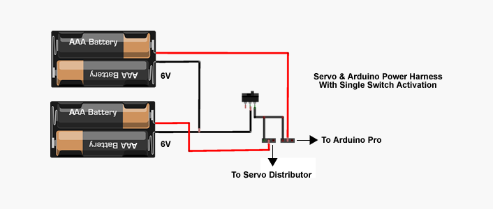
Fig 1: The Power harness circuit.
In my case, one of the servo plugs is then connected to the (optional) power header pin ports provided on the Arduino Pro (see featured image). However if you want to use a standard Arduino all you would need to do is replace one of the plugs with a compatible jack. The other plug is then connected to a custom built servo distributor board made using a 3 by 8 header pin connector with the positive (middle row) and negative pins (bottom row) all soldered together respectively. This means that when the plug is connected to one of the 8 columns positive and negative power connection is provided along the row (see fig 2).
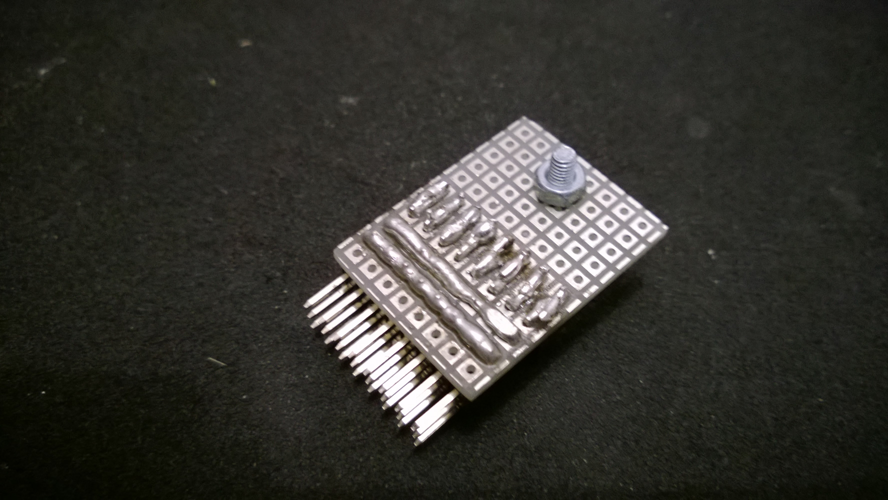
Fig 2: Bottom view of the servo distributor
The result is 7 available powered connections. All we need to do to operate/control the servo is utilise the final row on the distributor, to connect the signal line of each servo to the Arduino. In order to make each signal line as accessible as possible, I broke each one out to both a male and female header pin (see fig 3).
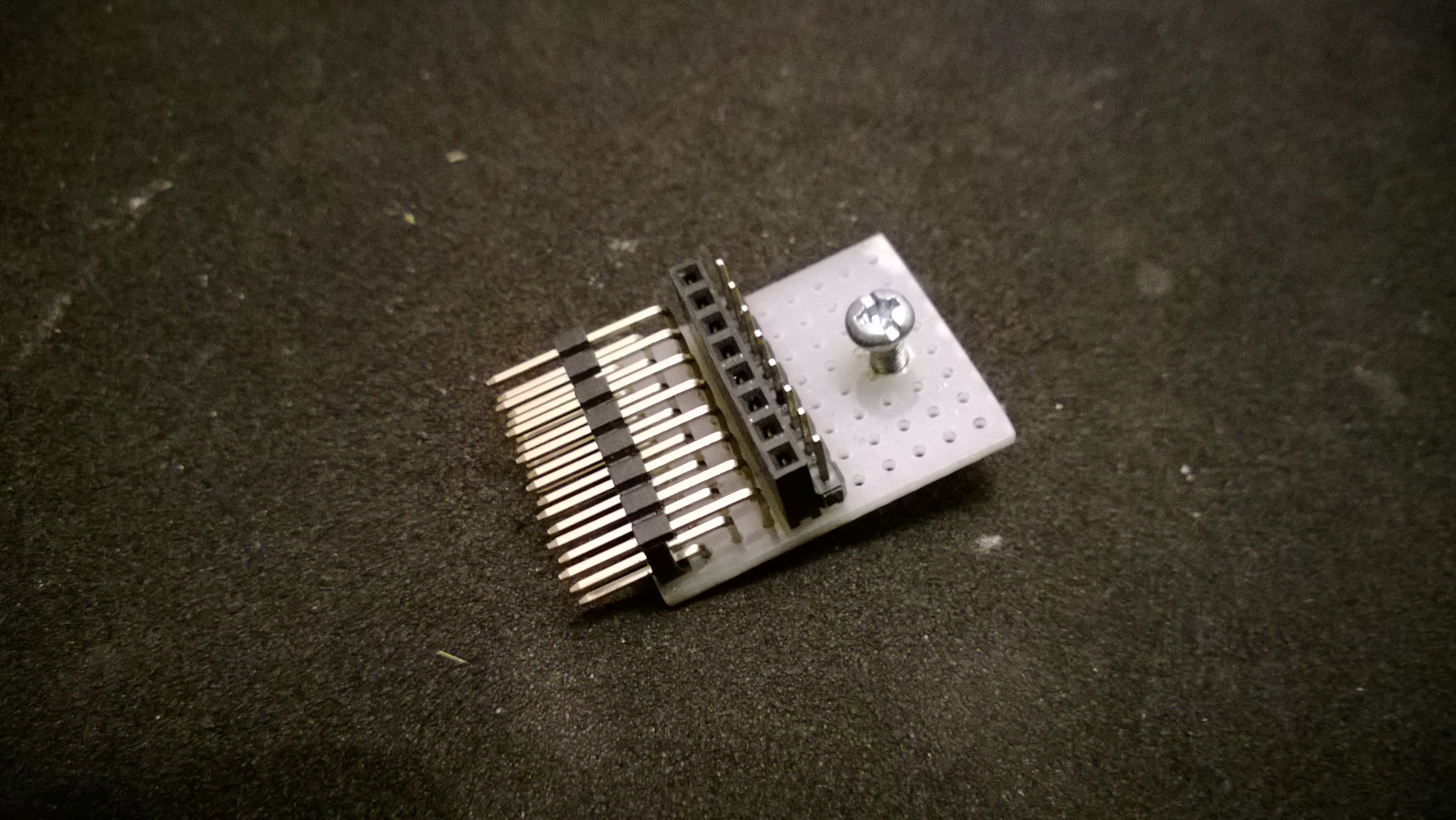
Fig 3: Top view of the servo distributor
In order to test the system I then wired both an led and mini servo up to the distributor (see featured image). Once I was happy that everything was working ok, I then attached the harness and batteries to Ratchets main body.
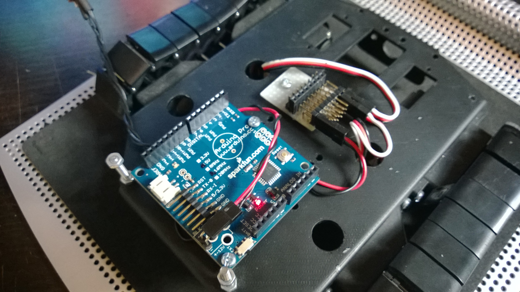
Fig 4: Mounted to body, top
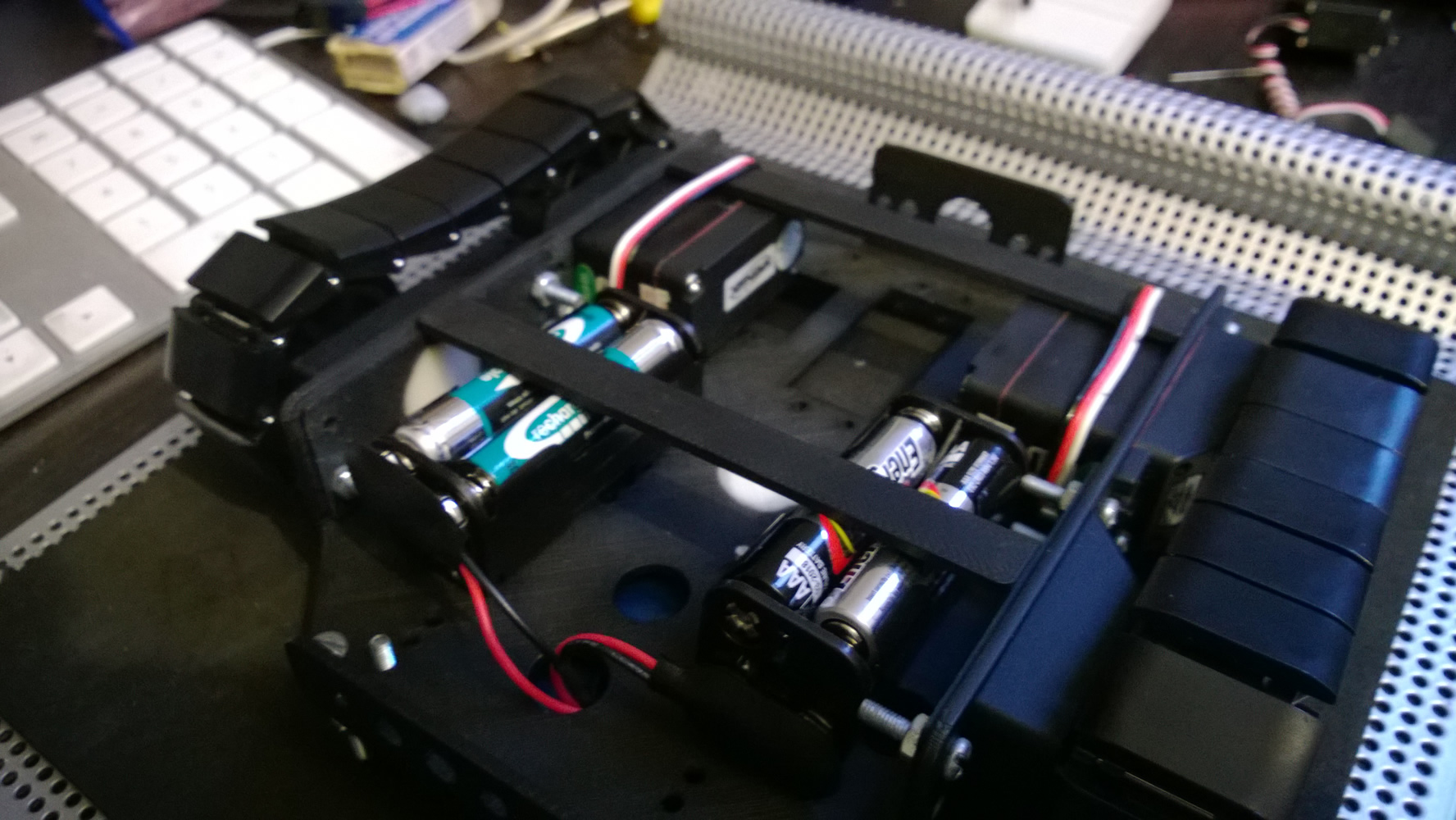
Fig 5: Mounted to body, bottom
Finally in order to really test the harness I then created a simple script that sends oscillating servo movement commands from the Arduino. The script is simply a clone of the Sweep Servo example that comes with the Arduino IDE, however expanded to cater for 4 Servos.
#include <Servo.h>

// create servo object to control a servo
// a maximum of eight servo objects can be created

Servo myservo1;
Servo myservo2;
Servo myservo3;
Servo myservo4;

// variable to store the servo position

int pos = 0;

void setup()
{
// attaches the servo on pin 9 to the servo object

myservo1.attach(9);
myservo2.attach(10);
myservo3.attach(11);
myservo4.attach(6);
}

void loop()
{
// goes from 0 degrees to 180 degrees in steps of 1 degree
// tell servo to go to position in variable 'pos'waits 15ms
// for the servo to reach the position goes from 180 degrees
// to 0 degrees

for(pos = 0; pos < 180; pos += 1)
{
myservo1.write(pos);
myservo2.write(pos);
myservo3.write(pos);
myservo4.write(pos);
delay(15);
}

for(pos = 180; pos>=1; pos-=1)
{
// tell servo to go to position in variable 'pos' waits 15ms
// for the servo to reach the position

myservo1.write(pos);
myservo2.write(pos);
myservo3.write(pos);
myservo4.write(pos);
delay(15);
}
}
Code 1: Simple servo test script
The following video shows the servos in action.
Video 1: Servo test run
As you can see all that I need to do is adjust the initial starting position of the servos on the final build and jobs a good un 🙂