ServoBot LED Headlight & Sharp IR Bumper
In this post I will demonstrate the assembly of the bumper for my current robot build Ratchet. The bumper contains both a Sharp IR distance sensor (for obstacle avoidance) and a pair of LED’s for headlights.
One of the key features that I liked about my last robot build Sheldon was the use of flashing combinations of the headlights to indicate information such as current mode etc. I found it so useful that I decided to duplicate this functionality for Ratchet too.
Fitting the Headlights
With this in mind I decided to wire up each headlight separately, and as the headlights are to fit to my ServoBot Shield I also decided to fit them out with servo plugs.
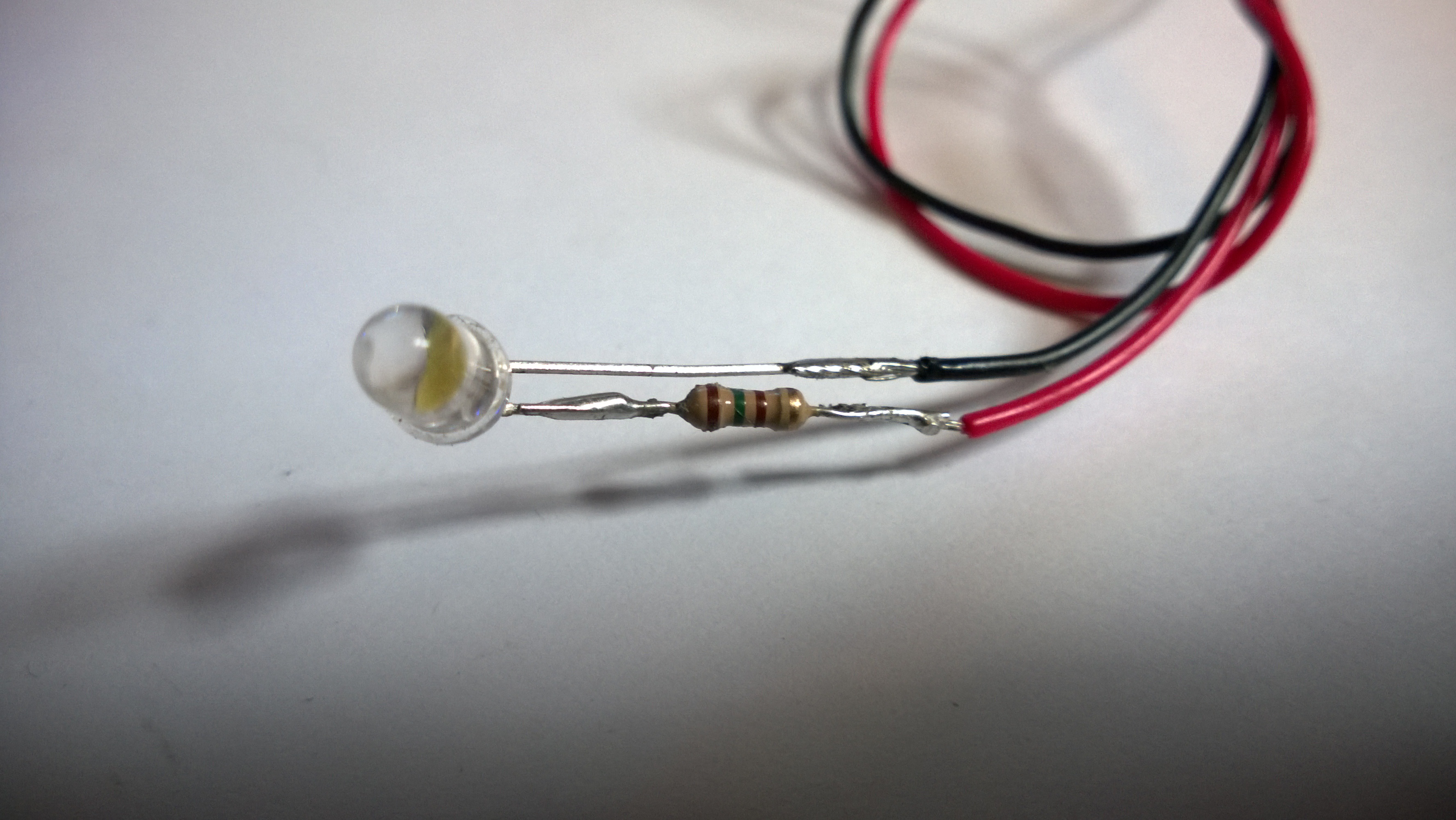
Figure 1: Led With 150R Resistor
This was done in a similar way as I wired up the Sharp IR sensors, however this time the LED’s positive leg is wired to the signal connector head and has a resistor wired in series to protect the LED (Figure 1).
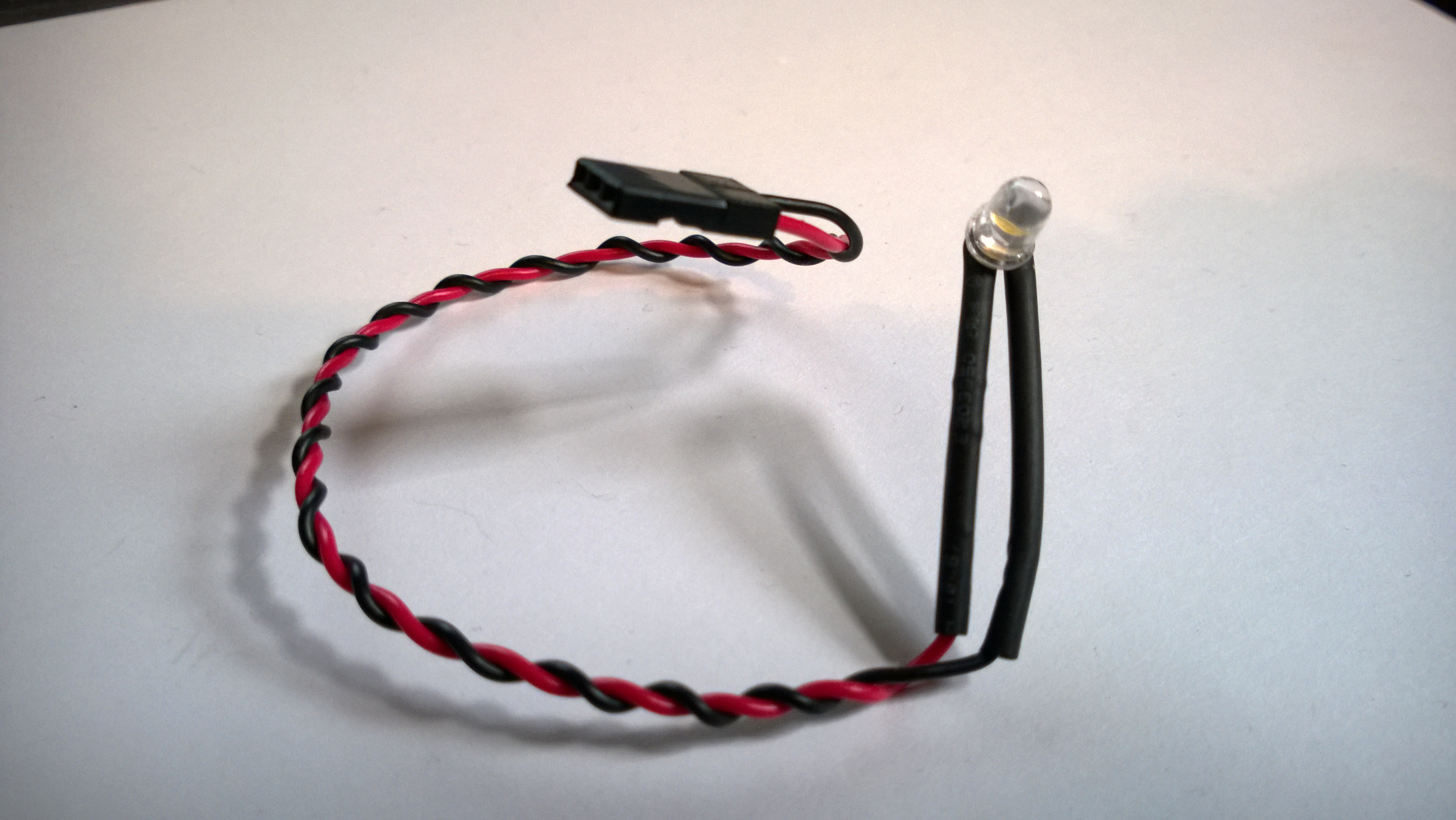
Figure 2: The completed LED with Servo Plug
The ground connector is wired as normal. This means that the LED will be powered by the Arduino and not the servo battery. Also this means that we can use the Arduino to turn the LED’s on and off via code. Figure 2 shows one of the completed LED’s with its connector.
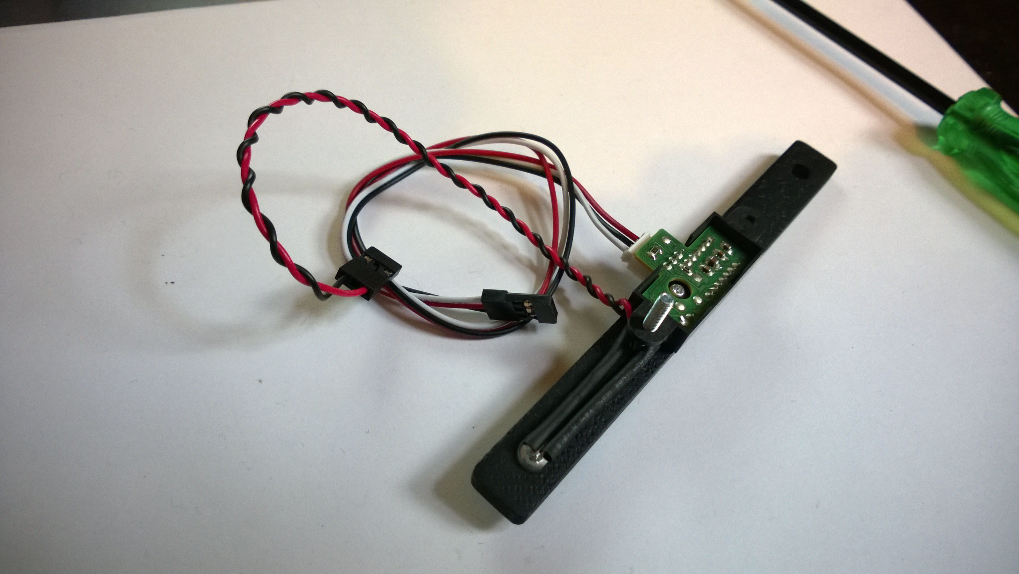
Figure 3: The Led Bumper Mounting
Mounting the LED’s to the Bumper
The LED’s simply mount to the bumper using a combination of both a friction fit in the provisioned hole, and securing via use of the Sharp IR’s casing (bit used for bolt) and its corresponding bolt (see figure 3). Figure 3 shows both a mounted LED and the Sharp IR from the back.
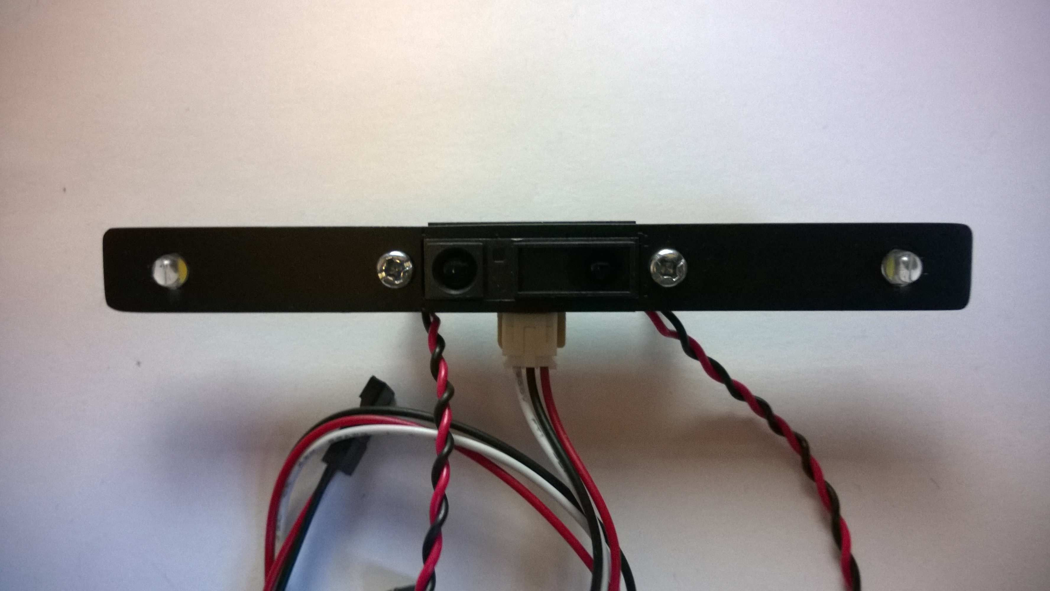
Figure 4: The Completed Bumper, Front
Figure 4 and figure 5 show the completed bumper ready for mounting. Before I began the mounting process however, I thought it would be a good idea to check the functionality of all the components. The Sharp IR was tested using the script demonstrated in my previous post.
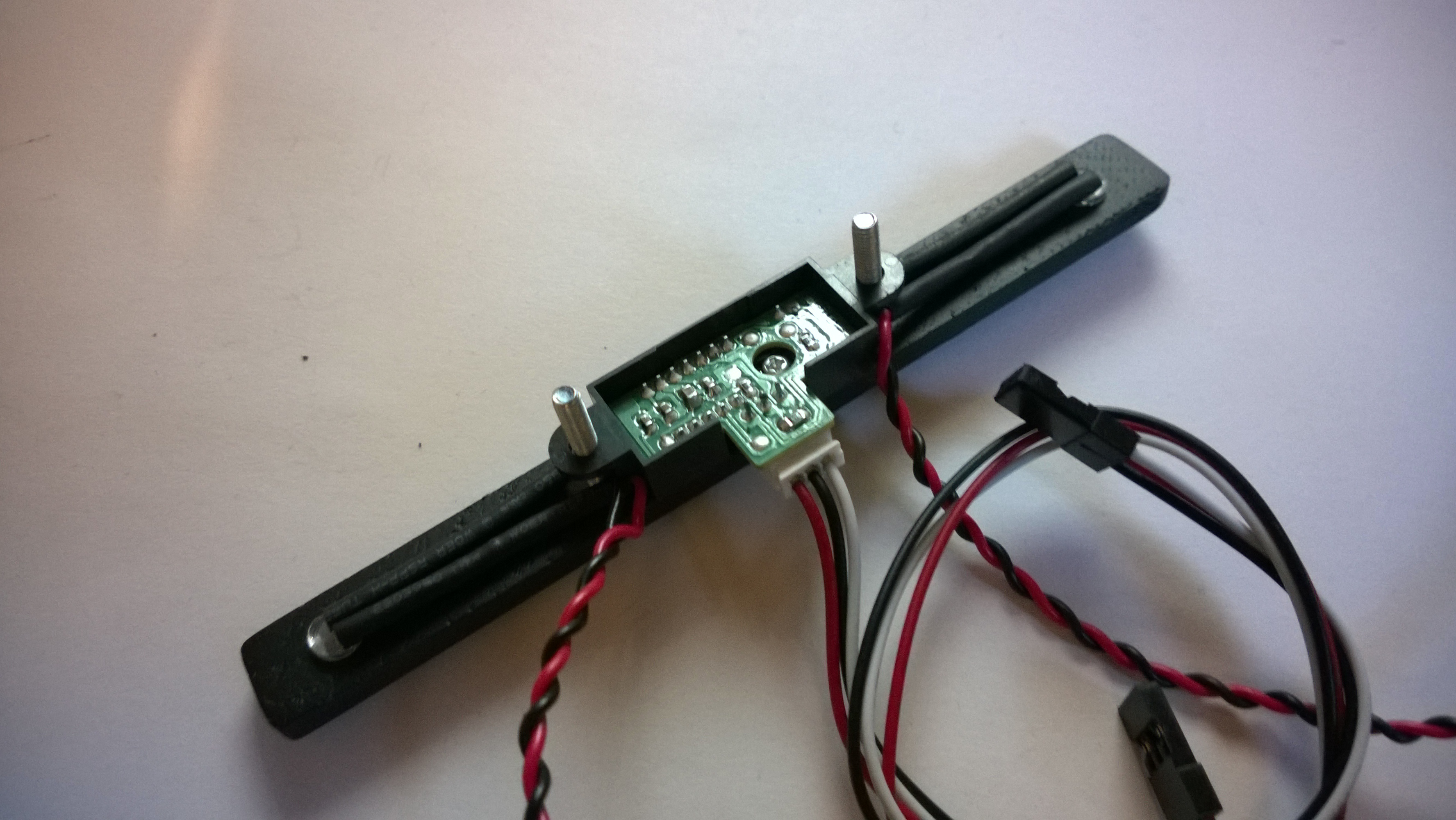
Figure 5: The Completed Bumper, Back
In order to test the LED’s however, I developed a new script based on the Blink example provided with the Arduino IDE. I simply modified the script to facilitate two LED’s and then connected the two servo plugs to the ServoBot Shield using the anolog pins A0 and A1. I have Included the script below for reference (code 1).
<pre class="brush: plain; collapse: true; light: false; title: ; toolbar: true; notranslate" title="">

/*
This script is based on the arduino Blink Script. It
Turns on both of ratchets LED's on for one second,
then off for one second, repeatedly.
 */

// Define the pins for
// each of the LED's

int ledR = A0;
int ledL = A1;

// the setup routine runs once
// when you press reset:

void setup()
{
  // initialize the pins as
  // an output.

  pinMode(ledL, OUTPUT);
  pinMode(ledR, OUTPUT);
}

// the loop routine runs over
// and over again forever:

void loop()
{
  // turn the LED's on (HIGH is the voltage level)

  digitalWrite(ledL, HIGH);
  digitalWrite(ledR, HIGH);

  // wait for a second

  delay(1000);

  // turn the LED off by making the voltage LOW

  digitalWrite(ledL, LOW);
  digitalWrite(ledR, LOW);

  // wait for a second

  delay(1000);
}
Code 1: Modified Blink Script
After verifying that both the LED’s and sensor worked, I then moved onto the task of connecting the completed bumper to Ratchet’s body.
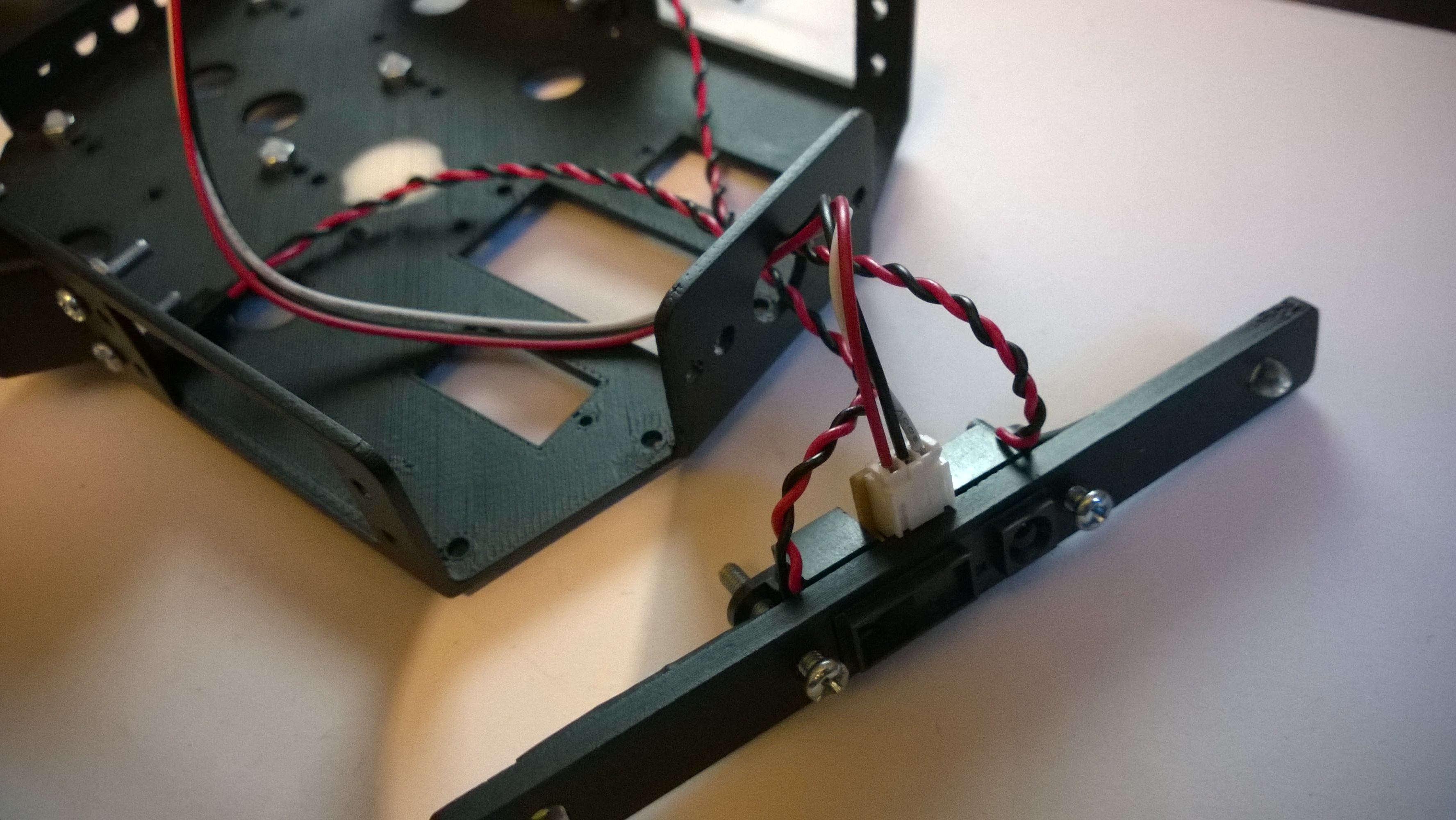
Figure 6: Mounting the Bumper to Ratchet
Mounting The Bumper
Thanks to Ratchet’s bolt together design, all that is needed to mount the bumper to the body is to:
First, ensure that each of the connectors and cables are threaded through the provided hole (fig 6). Then secondly, put the bolts used to mount the Sharp IR through the provided holes and apply a bolt to keep them securely in place.
With these mounting bolts in place the bumper is complete. Figure 7 shows the completed bumper.
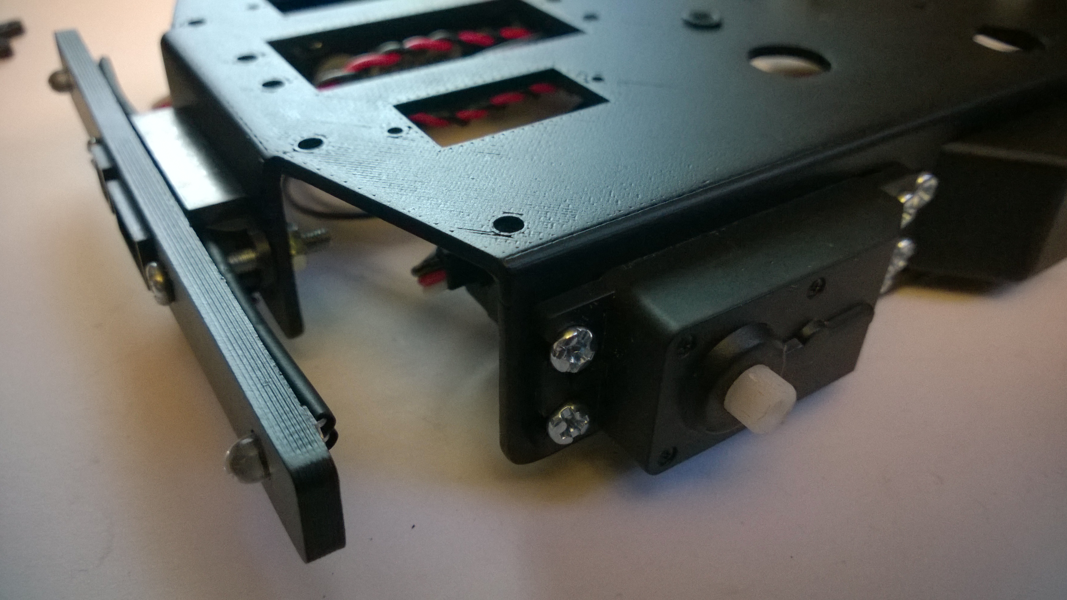
Figure 7: The Finished Bumper Mounted In Place
The primary function of the bumper is to provide Ratchet with distance data that can be used to prevent him crashing into objects when remotely or autonomously operated. Whilst it is true that I will be utilizing a phone camera over VOIP experience dictates that there may be occasions where the operator may miss something or a feed delay may result in a crash. The use of the Sharp IR shuld prevent both of these…. at least I hope… 🙂