Arduino Xbee Shield mod for Netduino
Update: For an alternative method check out the following post: /blog/xbee-explorer-regulated-netduino
This is a very quick post detailing how I modded my netduino to be compatible with the arduino xbee shield. I utilize this shield in conjunction with a Sparkfun Xbee Explorer USB to provide wireless serial communication between netduino and PC. To find out more about that check out my SerialPortHelper to WinForm post.
The following image shows the completed mod in action.
The good news is that there is not much to this one, however some might find the thought off using a soldering iron on there netduino a bit scary. If this is you then there are always other options.
In order to get the two boards to communicate you need to add six header pins to the square block situated at the end of the netduino (the 6 gold circles in two rows of three). I did this by attaching two strips of three cut from a 40 pin header row. To see this in situe check out the following images.
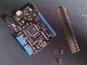
Fig 1: Header Pins
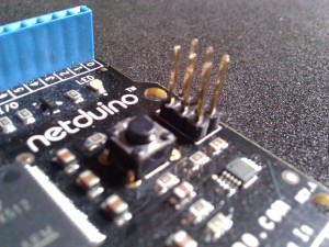
Fig 2: The Attached Pins
Finally you need to ensure that both of the jumpers on the shield are set to XBee rather than USB. In order to do this set the jumpers so that they the two pins towards the interior of the board. To see this in situe check out the following image.
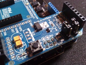
Fig 3: Jumper Pin Positions
One slight disadvantage of the shield is that it covers the netduinos stack-able header power block. To rectify this I also fabricated two additional header (male/female) sets which can be interchanged depending upon my needs. Both are shown in the following images.
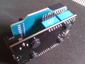
Fig 4: Header Block Mod Male
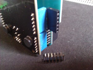
Fig 5: Header Block Mod Female
These headers enable me to still have access to those covered by the shield. For more information on the shield check out the ArduinoXbeeShield page here.