A Circuit-python Library for the PAA5100JE
Recently I have been playing around with several RP2040 based micro-controllers in order to investigate the RP2040 as a platform for an upcoming project. During my studies I have found that because the RP2040 itself is still fairly new; there is not that large an amount of compatible libraries for existing sensors and breakouts yet. The libraries do exist; just for other platforms such as Arduino and Raspberry PI.
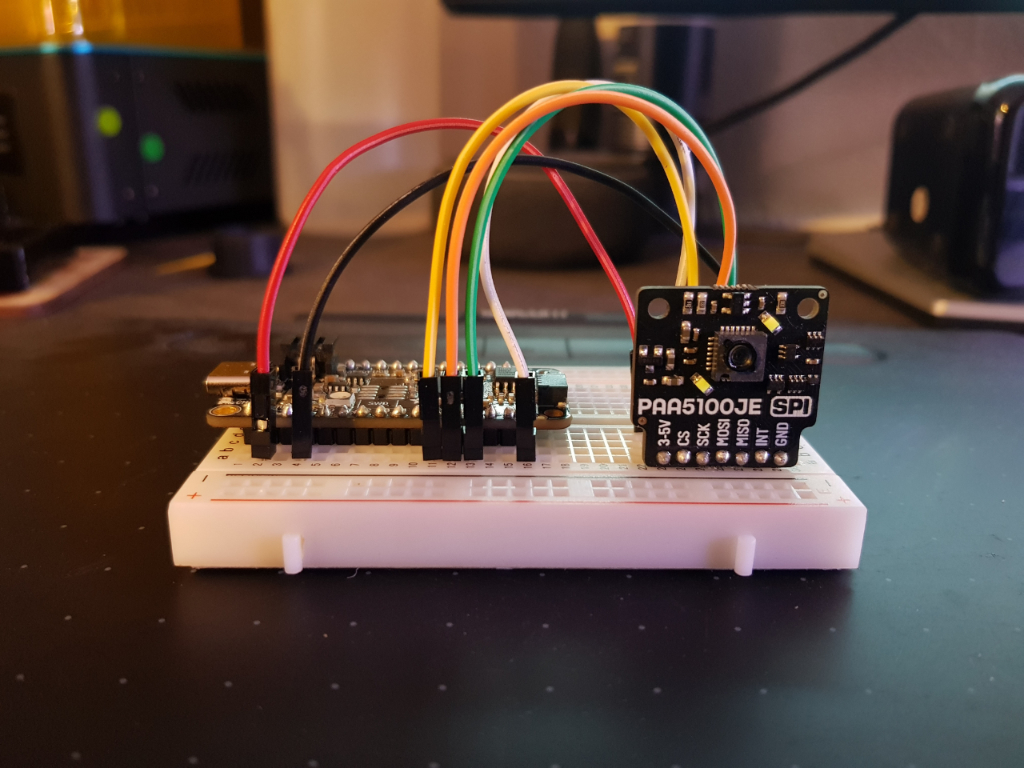
 Figure 1: The PAA5100EJ connected to a Feather RP2040
The PAA5100JE optical flow sensor is one such sensor; more importantly, its a sensor I also want to use for the aforementioned (top secret) project. With all this in mind; the only thing for it, was to have a go a porting an existing library over to circuit-python. I chose circuit-python because I want to utilise its HID capabilities further on in the projects development. This decision also had the knock on effect of highlighting the python library for the PAA5100EJ developed by Pimoroni as the best starting point for the project.
Luckily the port was successful and this post outlines how you can use the code in your own projects. It also highlights some of the discoveries and decisions that I made along the way so that I can refer to them in the future.
Prerequisites
Before you can use the code you will need to ensure you have several prerequisites. Assuming you already have a Circuit-python installation, you will also need to install the Adafruit_Circuit_BusDevice library. This library can be located via the previous link or installed via the following pip command:
pip3 install adafruit-circuitpython-busdevice
Command 1: Installation via pip3
Installing the code
The projects github repository contains two circuit-python files: code.py and pa55100ej.py. For those familiar with Arduino; the code.py file is the equivalent to an arduino sketch file in that it is where you put your main code that you want to run. Similarly pa55100ej.py is like an Arduino library called by the main code.py file. These are all you will need to get things up and running.
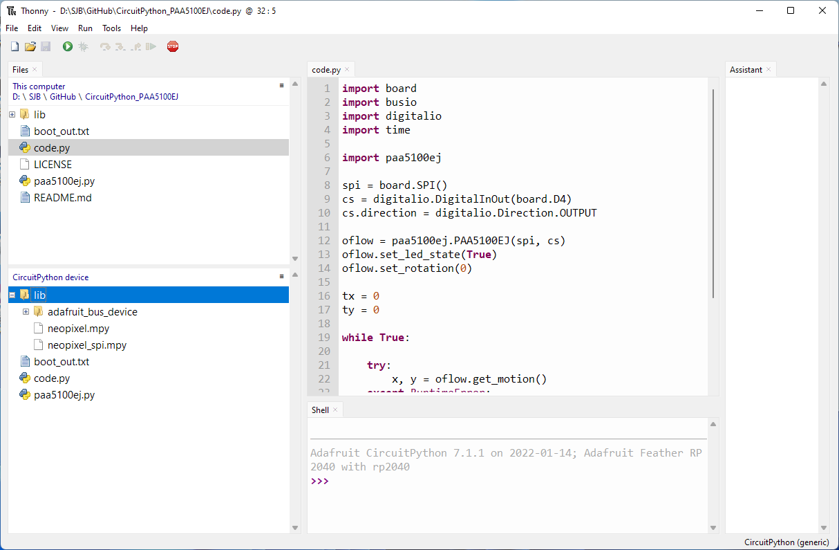
 Figure 2: Installation setup and file structure
Once you have obtained the files you then need to place the file paa5100ej.py in your circuit-python drives designated library location; and also the file code.py in its required location. For the latter this is usually the root. For the former its usually a bespoke library directory also created at the root of the circuit-python drive. Figure: 2 shows my installation setup and file structure within the Thonny IDE. For reference: the lib directory contains the Adafruit_Circuit_BusDevice library library as detailed in prerequisites.
For my setup, I have also two neopixel libs included in the directory as I am using a Feather RP2040 board which has an on-board neopixel. This I annoyingly need to turn off at every boot. If you don’t have the same board, i.e. you are using a pi pico then you shouldn’t need these libraries.
Using the code
With the installation/setup complete; lets move on to putting together the circuit and also having a look at the code itself.
A look at the circuit
First up we connect the sensor to the micro-controller. As I am using the Feather RP2040 I use the connections shown in Code: 0. These will be similar for whichever RP2040 board you use. Just make sure to check your boards corresponding pin diagram.
3-5V - 3.3V
CS - D4
SCK - SCK
MOSI - MO
MISO - MI
INT -
GND - GND
Code 0: The sensor to Feather RP2040 connections
With the connections made lets move onto having a look at the code.
A breakdown of code.py
The only code you really need to worry about in order to get things working in your own application is that found within code.py. To this end this section takes a look at the file in detail. So it can be adapted for your own needs.
First up we import all the libraries/modules that we will need. These are:
The board module; which contains constants for the pins on the specific board we are using. The busio module which contains classes to support a variety of serial protocols such as SPI and I2C. The digitalio module to provide access to the boards pins. The time module to allow for use of time and timing related functions. Finally we include the pa55100ej library to allow us to interface with the pa55100ej sensor using SPI.
import board
import busio
import digitalio
import time
import paa5100ej
Code 1: code.py module/library imports
Once we have imported all the required modules/libraries we then create a reference to the boards SPI hardware bus. This is then passed to the paa5100ej library where it is used to create a new SPIDevice using the SPIDevice Library.
spi = board.SPI()
cs = digitalio.DigitalInOut(board.D4)
cs.direction = digitalio.Direction.OUTPUT
Code 2: the SPI and CS definitions
In addition to the boards SPI configuration a custom chip select pin is also passed to the class. The CS pin is one which can be toggled to tell the chip that it should listen and/or respond to requests on the SPI bus. This toggle can be controlled manually by code; however by using the SPIDevice Library this is handled for us automatically. More Information on the library can be found here and here
Next we initialise and make a reference to the paa5100ej class. As we do so we pass to it both the aforementioned references to the SPI and CS pins. The class then utilises this information to create a new SPIDevice that handles the SPI interface and allows us to communicate with the sensor.
oflow = paa5100ej.PAA5100EJ(spi, cs)
oflow.set_led_state(True)
oflow.set_rotation(0)
Code 3: Initialising the PAA5100EJ
Finally we create two properties to store any movement outputted from sensor in both the x and y direction. These properties are updated each loop of the main class as a means of storing the cumulative movement detected by the sensor.
tx = 0
ty = 0
Code 4: The tx, ty properties
With our setup complete lets move onto the main loop. If we take a look at our main program (Code: 5) we can see that it consists of a loop which is kept alive via the use of a while true statement. On each iteration of the loop a call is made to the pa55100ej class via the get_motion() function. Any iteration where data is not available is accounted for via wrapping the call in a try block.
A caught exception causes the loop to continue. If data is received this is assigned to the x and y variables which are in turn used to update the values of tx and ty.
while True:

    try:
        x, y = oflow.get_motion()
    except RuntimeError:
        continue

    tx += x
    ty += y

    print("Motion: {:03d} {:03d} x: {:03d} y {:03d}".format(x, y, tx, ty))
    time.sleep(0.01)
Code 5: The update loop
A print command is then used to output the data to the console and/or serial. The command applies simple formatting so that each value is shown to 3 decimal places. Finally we then use a time.sleep() command to provide a pause and to slow things down for brevity.
A look pa55100ej.py
The pa55100ej.py is almost a direct port of the Pimoroni PMW3901/PAA5100EJ sensor library. The main changes are around the structure of both the data read and write commands. Within each of these I had to convert the spi_dev.xfer2() method to one that is available within circuit-python.
def _write(self, register, value):
    GPIO.output(self.spi_cs_gpio, 0)
    self.spi_dev.xfer2([register | 0x80, value])
    GPIO.output(self.spi_cs_gpio, 1)
Code 6: The original write method
For the write this was easily achieved by wrapping the register and value to be called correctly within a bytearray and passing it via spi.write(). The other key thing to note here when comparing the two code blocks (6,7) is the lack of commands required to toggle the CS pin within block 7. As indicated this is thanks to the SPIDevice library which is handling this for us.
def _write_to_reg(self, reg, val):
    with self.spi_device as spi:
        spi.write(bytearray([reg | 0x80, val]))
Code 6: The circuit-python write method
The read command was a little more difficult; my investigations resulted in two methods based around spi.readinto() and spi.write_readinto().
 def _read(self, register, length=1):
    result = []
    for x in range(length):
        GPIO.output(self.spi_cs_gpio, 0)
        value = self.spi_dev.xfer2([register + x, 0])
        GPIO.output(self.spi_cs_gpio, 1)
        result.append(value[1])
Code 7: The original read method
The latter is the one needed within the script to replace the original spi_dev.xfer2() call within the _read() method of Pimoroni code (7).
def _read(self, register, length=1):
    result = []
    with self.spi_device as spi:
        for x in range(length):
            val = bytearray(2)
            cmd = bytearray(2)
            cmd[0] = register+x
            cmd[1] = 0
            spi.write_readinto(cmd, val)
            result.append(val[1])

        if length == 1:
            return result[0]
        else:
            return result
Code 7: circuit-python read method
In order to get the code to function properly I had to break it down into parts. There is probably a more efficient means of doing this; but hey I’m new to the language. I must note that my inspiration/motivation for this came from this post over on the micropython.org forums. This little nuget of information was the glue that brought everything together.
def _register_read(self, register, length=1):
    with self.spi_device as spi:
        spi.write(bytearray([register]))
        result = bytearray(length)
        spi.readinto(result)
        return result
Code 8: circuit-python readinto() method
For completeness code: 8 shows the spi.readinto() method. This may be useful in the future when I once again attempt a similar undertaking. The method first performs a write to a specific register (register) and then reads into a bytearry (result) of a set length (length).
A quick look at the documentation suggests there is no need for a separate write command and this could be amended as shown in Code 9; however I haven’t tested this yet! TBH I missed it when I wrote the code (hey im a python and circuit-python noob remember!).
def _register_read(self, register, length=1):
    with self.spi_device as spi:
        result = bytearray(length)
        spi.readinto(result, register)
Code 9: circuit-python readinto() amended
The final differences between my code and its Pimoroni python counterpart are around the register initialisation code. Firstly I removed the register code required to use the library with a PMW3901 sensor. This however can easily be added back in. Thanks to my having separated each of the initialisation calls into chunks:
self._init_registers_secret()
self._init_registers()
self._init_registers_led()
Code 10: Initialisation of registers
All you would need to do is swap out the register values defined within the _init_registers() method with those that can be found within the Pimoroni pmw3901 class.
Secondarily is the inclusion of a method to toggle the state of the sensors onboard led’s (Code: 11). All this method does is to write a differing value to register 0x6f in order to toggle the lights on or off. I also broke out the led initialisation into its own method (see Code: 10) so that functionality can be controlled upon initialisation. The register and values and code for the led toggle call were located via this issues post.
def set_led_state(self, state=False):
    if state == True:
        self._bulk_write([
        "WAIT", 0xF0,
        0x7f, 0x14,
        0x6f, 0x1c,
        0x7f, 0x00
        ])
    else:
        self._bulk_write([
        "WAIT", 0xF0,
        0x7f, 0x14,
        0x6f, 0x00,
        0x7f, 0x00
        ])
Code 11: The set_led_state() method
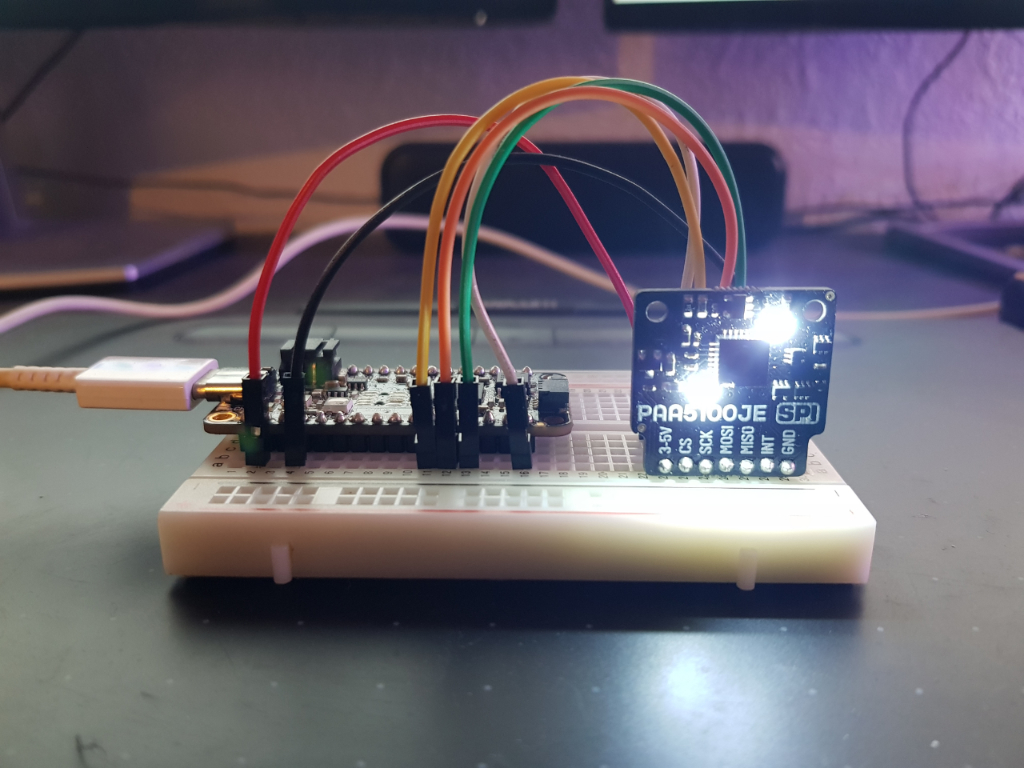
And thats it. Hopefully there is enough there to enable you to use the library with your own PA55100JE and Circuit-python implementations. If all goes well when you play the code you should end up with some glaring lights like those shown in Figure: 3. Additionally a stream of data will be present via serial!
As always if you need any more info I can be contacted by the socials. Your best option would be to open an issue here. As I progress with the building of this Github Pages site I aim to implement comments via use of utterances so eventually your comments/questions may also show up here.
As a final note; i don’t think i will ever get used to not having to terminate statements :)
Updates
NB: Since completing the library I discoverd an official Pico one for Micropython by Pimoroni so that may be a better option for you? This can be found here Although it looks like there may be a few more hoops that will need to be jumped through to get things up and going etc (see their readme for more details).
I have also updated the github repository to include the capability for the initialisation of the registers for a PWM3901 sensor. To swap between the PMW3901 and the PAA5100EJ; just un-comment/comment the corresponding init_registers method. See Code: 12 for more details.
"""Initialize the device registers. You don't seem to need
the secret ones for the PAA5100EJ!?"""

self._init_registers_secret()

""" You can now chose between either the the PAA5100EJ or the PMW3901.
    Just un-comment/comment the corresponding init_registers method"""

self._init_registers_PAA5100EJ()
# self._init_registers_PMW3901()
Code 12: Initialize either device registers
Finally I have also added the code as outlined in Code: 9 to the script in a method called _register_readinto(). I’ve not tested this yet but it compiles etc.
