Ratchet Headstock Assembly
Here we have another posting on the on-going build of my robot Ratchet. This time around I will detail the construction of the headstock assembly and present a simple script developed to help with the alignment of servos. The good news is, is that this is the final task in terms of hardware assembly.
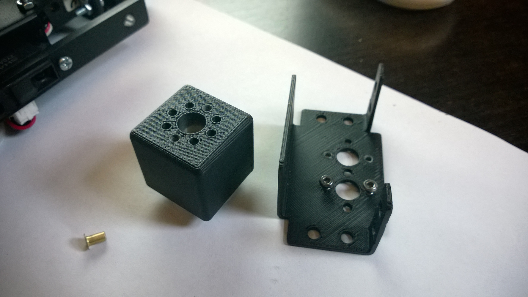
Figure 1: The Headstock Neck Components
The headstock consists of two separate sections (neck & head) each with its own servo. When combined these two sections allow for both Pitch and Yaw movement.
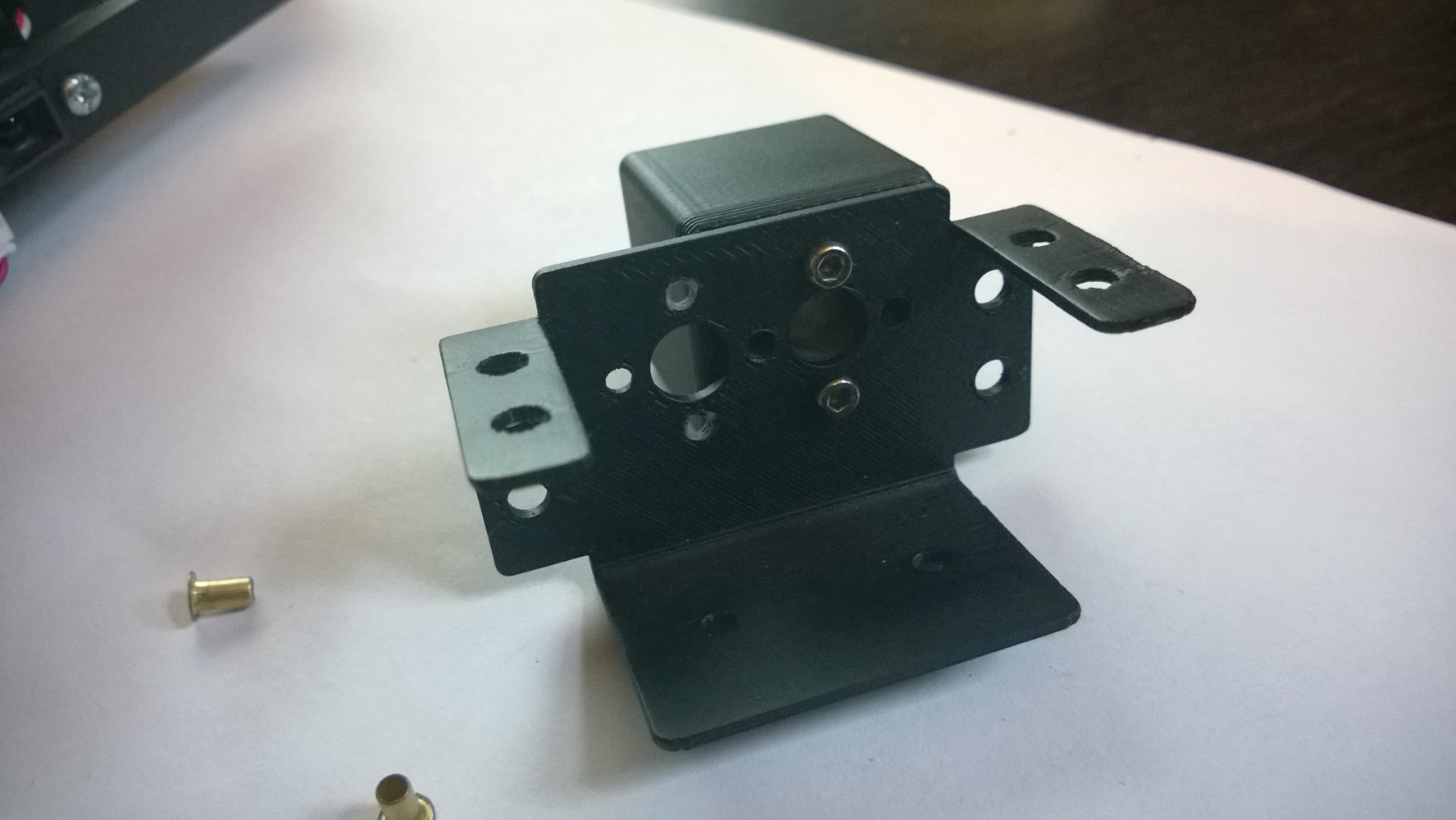
Figure 2: The Assembled Neck
The assembly of the headstock begins with the Neck section. This is easily completed by bolting together the two parts as shown in figure 1. Figure 2 shows the completed Neck assembly.
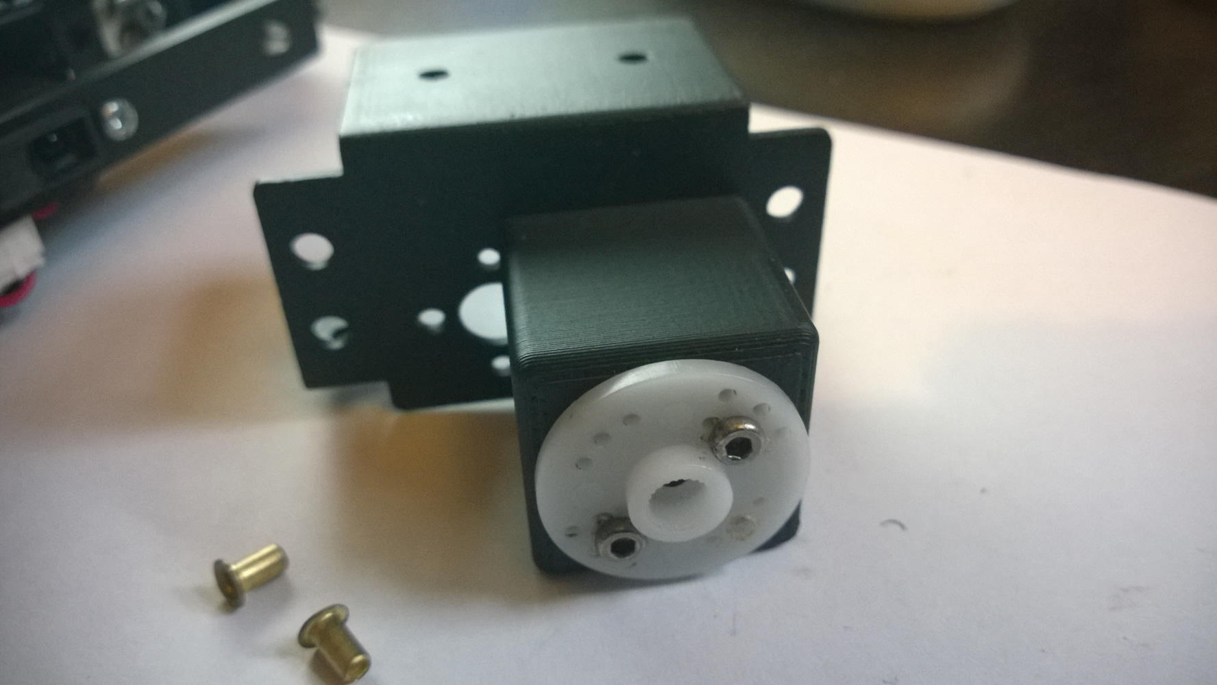
Figure 3: The Neck Servo Horn
Attaching the Neck Servo Horn
With the neck assembly complete, the final thing that we need to do is attach a servo horn to its base. This allows us to connect the neck and in turn the headstock to the servo mounted within the base unit. The servo horn is simply held in place via two bolts as shown in figure 3.
Aligning the Servo for Mounting
Before the servos can be mounted to the headstock they need to be aligned. In order to do this I developed a simple script that allows me to set a defined servo to a desired angle.
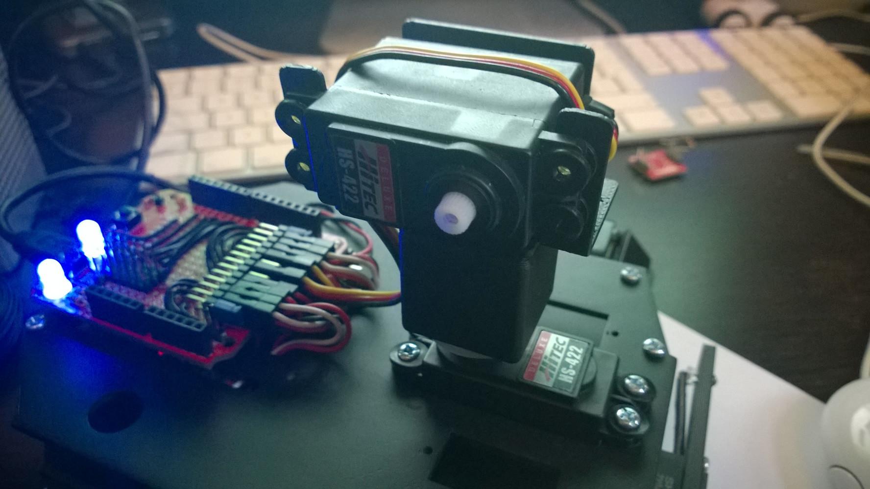
Figure 4: Aligning the Servos
I have included this script for reference below (code 1). NB: The script also lights the LED’s so I could double check that they still work.
As always, I have also commented the code so that you can hopefully follow how it works. With the servos aligned, I then moved onto assembling the pitch attachment and phone mount.
<pre class="brush: plain; collapse: true; light: false; title: ; toolbar: true; notranslate" title="">

/*
This script turns on both of Ratchet's LEDs and resets
the assigned servo to a defined angle. This script is
used to align the servos for the headstock
*/

// Include the Arduino
// servo control lib

#include

// create servo object to control a servo
// by default a maximum of 6 servo objects
// can be supported by the ServoBot Shield

Servo myservo;

// The angle you want the
// servo to be set to.

int val = 90;

// Define the pins for
// each of the LED's

int ledR = A0;
int ledL = A1;

void setup()
{
  // Set the LED pins to output

  pinMode(ledL, OUTPUT);
  pinMode(ledR, OUTPUT);

  // Set both pins to high to turn
  // on the LED's

  digitalWrite(ledL, HIGH);
  digitalWrite(ledR, HIGH);

  // Attach the desired pin to the
  // defined servo.

  myservo.attach(6);

  // Tell the servo to go to the
  // desired angle

  myservo.write(val);
}

void loop()
{
  // do nothing, we are done! Or keep
  // writing to the servo (uncomment)

  // myservo.write(val);
}
Code 1: Servo Alignment Script
First I began by bolting the phone mount onto the pitch head with two bolts (figure 5). Once this was completed I then attached this assembly to the Neck assembly.
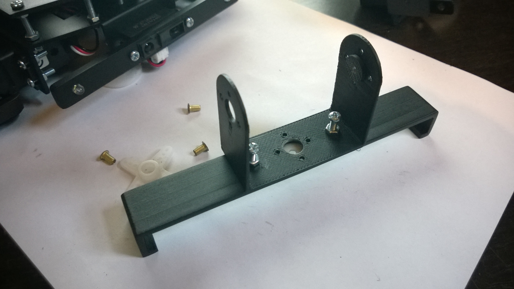
Figure 5: Pitch Head & Clip Mount
This is a simple process that consists of attaching bolt through the pitch mount and screwing it into the corresponding hole on the pitch head (figure 6).
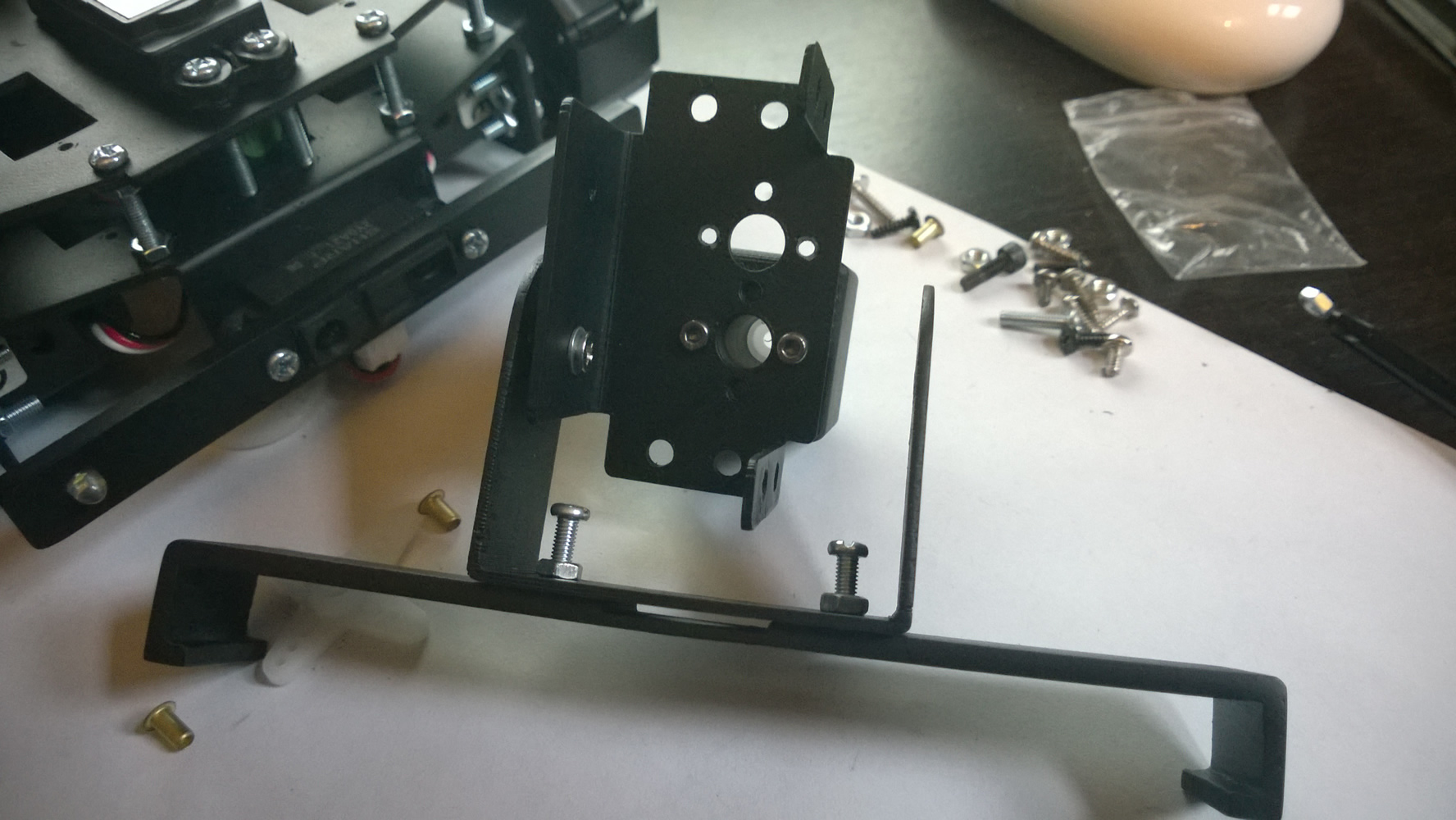
Figure 6: Completed Assembly With No Servo
I then proceeded to attach the headstock to Ratchet via the servo horn (figure 3) and secured it in place with the provided screw. Fortunately I got the sizes right and the screwdriver fitted down the shaft with no issue 🙂
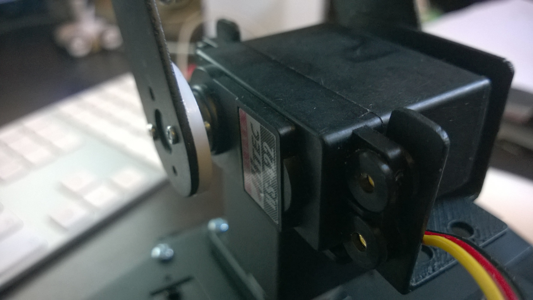
Figure 7: Attaching the Pitch Servo
Attaching the Pitch Servo to the Headstock
The final stage of the build is to attach the servo to the headstock that controls the headstock’s pitch. This is achieved by first attaching the horn to the servo and screwing it into place. Once complete, the pitch head is then secured to the horn using two small screws as shown in figure 7.
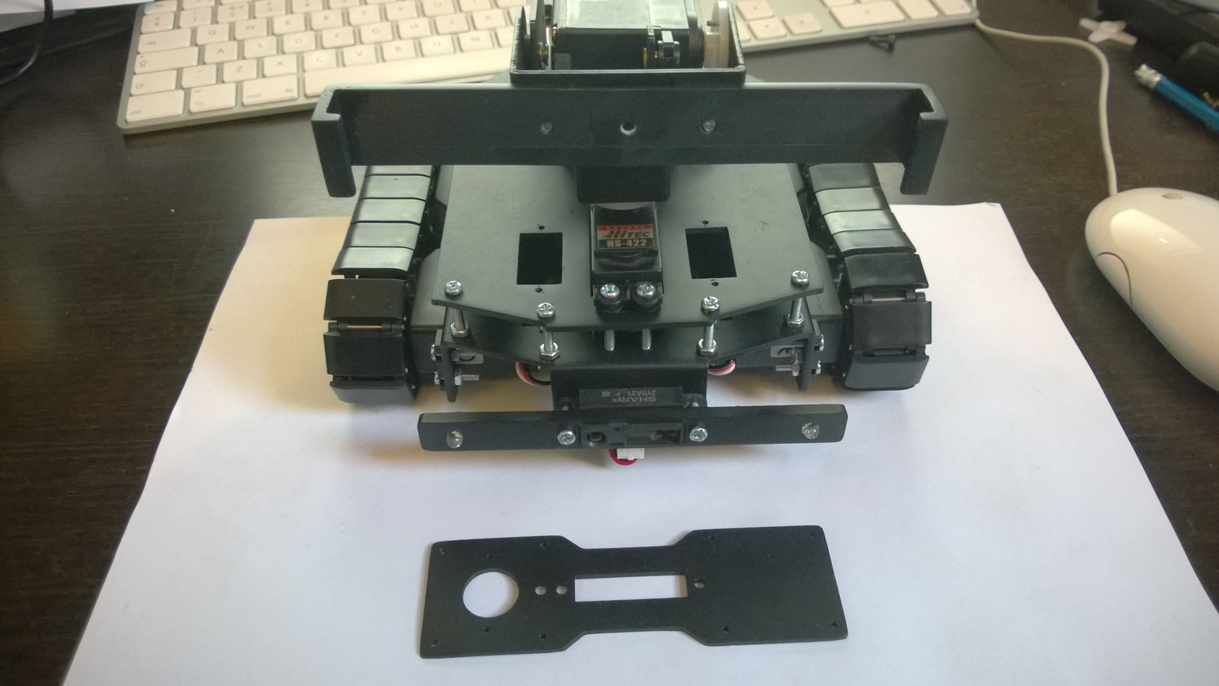
Figure 8: The Completed and Mounted Headstock, Front
The servo is then attached to the mounting bracket with servo mounting grommets and inserts. These are the rubber rings and the brass metal pins as can be seen in the featured image from the back, and within figure 7 from the front. With the servo in place Ratchets headstock is completed.
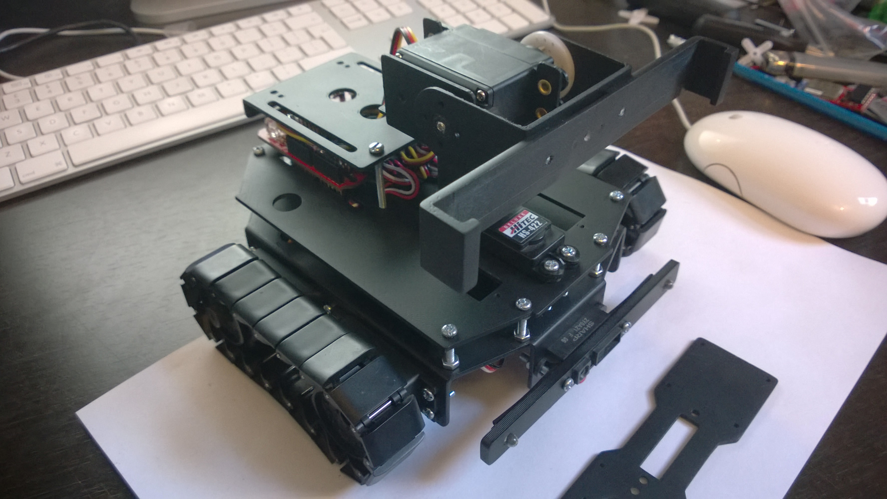
Figure 9: The Completed and Mounted Headstock, Isometric
The above image (figure 8) shows Ratchet with the completed headstock. Also included within the image is an additional face plate which can be swapped in instead of the camera mount if required. This plate is the same one as used in my previous robot build Sheldon and will allow for an additional IR sensor and WIFI camera to be used instead of the phone if desired.
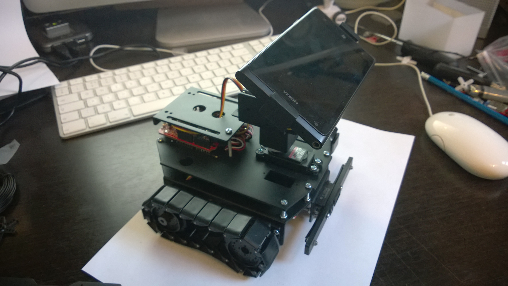
Figure 10: The Completed Headstock With Phone
As a taster of what’s to come, the final image (figure 10) shows the completed headstock with a Nokia WP7 attached. Thats it for now, and don’t forget to checkout my facebook page intermediary updates and extras 🙂