The ServoBot Shield
Last month I published a post detailing the construction of a power harness for my servo based robots Ratchet and Clank. The harness is used to connect one of two battery sources to either an Arduino or a simple power distribution board (PDB). The PDB, much like its qauadcopter equivalent, is a simple board that is used to distribute power across each attached servo, whilst also breaking out each their signal lines so that they can easily be connected to the Arduino.
During the publication of that post I began thinking; why have a separate board with all those wires? Why-not just put together a simple shield that does the same thing in a more compact manner? After toying around for a while with the idea I came up the design for my very first ever shield, The ServoBot Shield.
Introducing the ServoBot Shield
The shield simply duplicates the functionality of the distributor board whilst also breaking out an additional six digital pins which can be connected to via servo plugs. This affords capability for the connection of a 6 channel RC receiver (vertical pin block, fig 1), or simply just servo style powered connections for components such as sensors or LED’s. Also, thanks to using a Sparkfun ProtoShield Kit for the body of the design, provision for a BlueSmirf Bluetooth connection is also afforded (see fig 2).
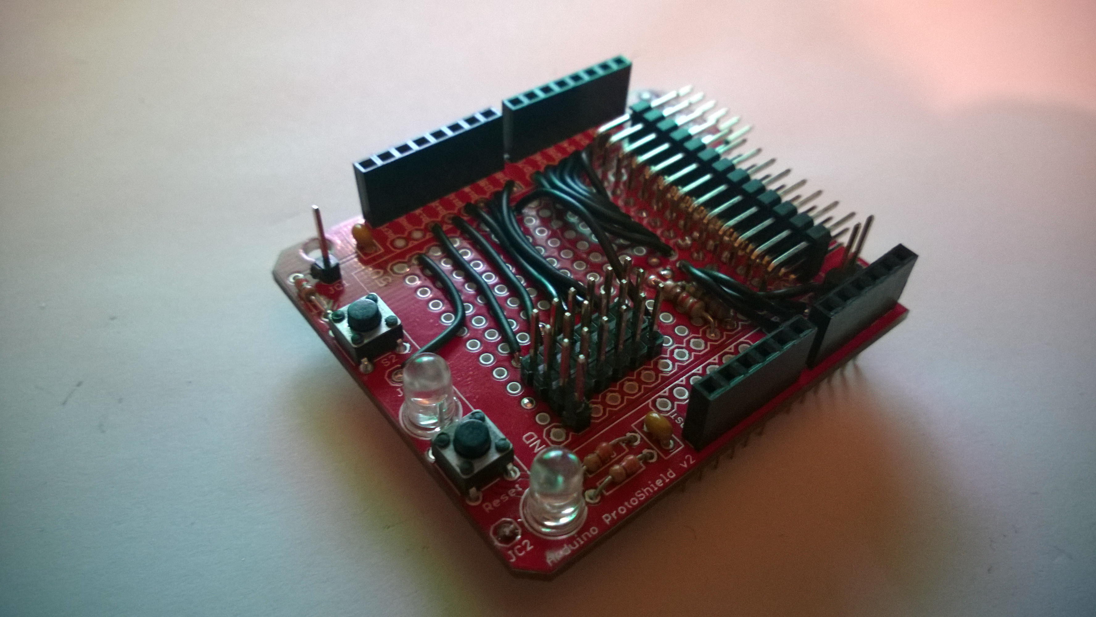
Fig 1: Vertical pin block (RC)
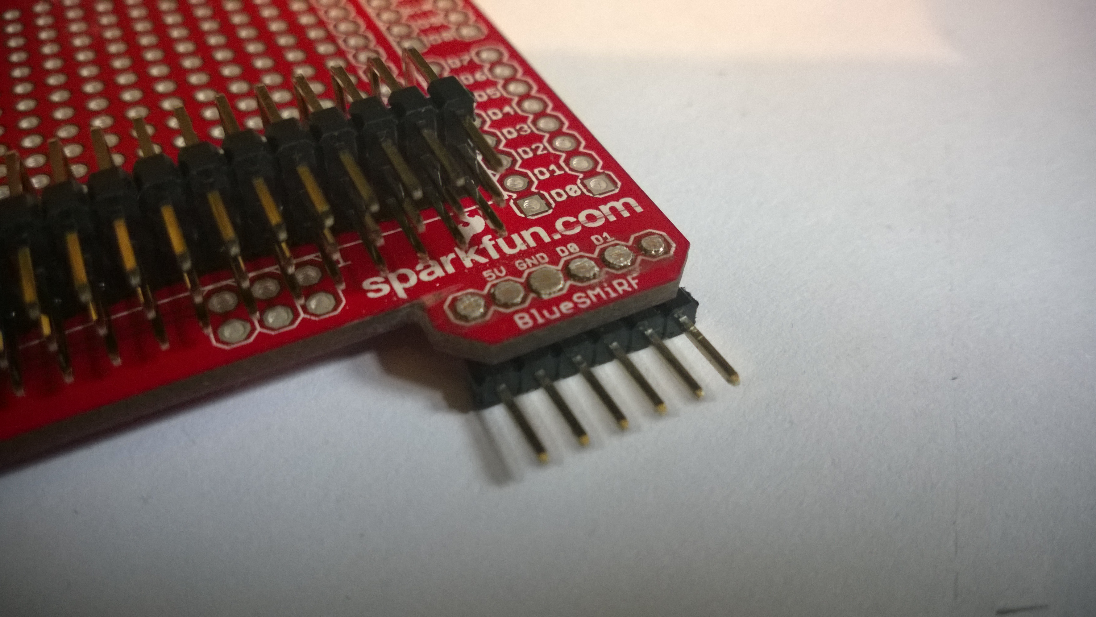
Fig 2: BlueSmirf Connection
In the same manner as with the aforementioned six digital pins, the board also breaks out four of the Arduinos analog pins to allow them to be connected to via servo style connection heads. Two of these anolog connections are also tied to ground via a resistor so that capability is afforded for the connection of sensors which require voltage division such as Spectra Symbol Flex Sensors.
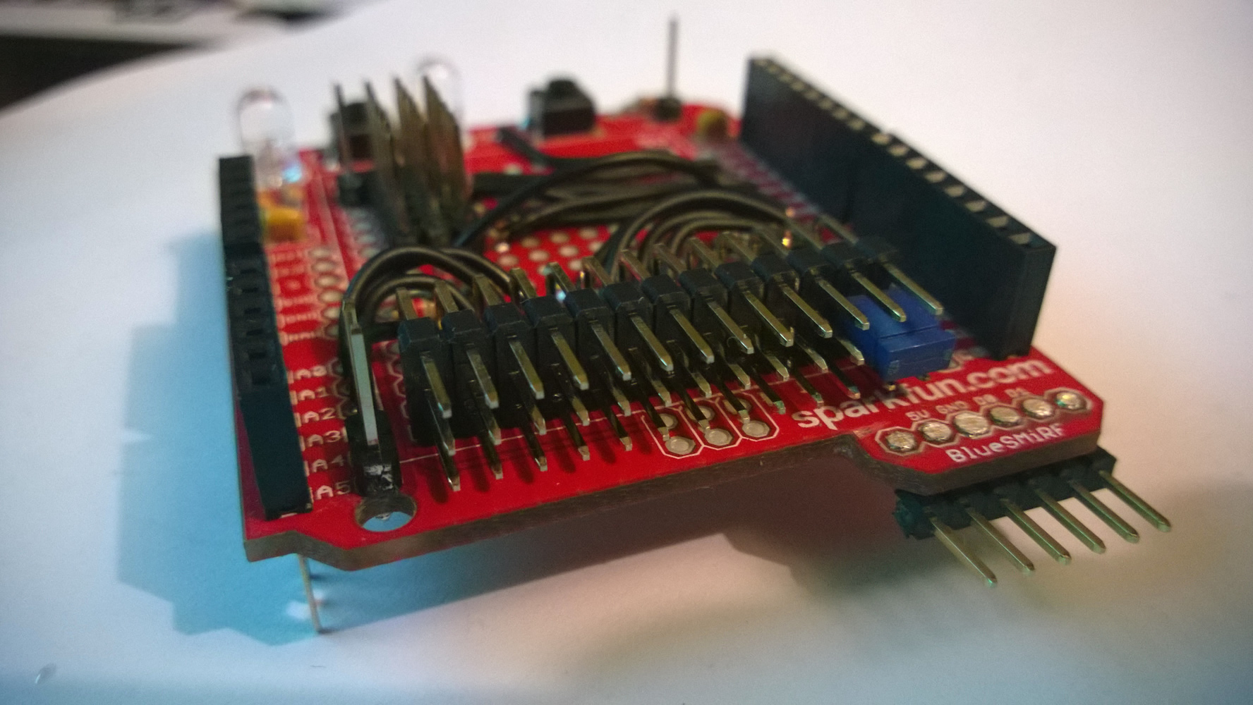
Fig 3: The Power Jumper
The final feature of the board is the provision of an extra pin row soldered to the ProtoShield boards 5V line allowing for the board to provide power to the main digital pin (primarily servo) connections via use of a jumper (Fig 3).
This means that you can either power the servos via the Arduino (not recommended) or even just connect to the digital pins via a powered servo head type connection.
The only other thing to mention is that I have also broken out the pin required for the operation of the switch that is included with the Arduino ProtoShield. This means that it is available for connection if required, and can be tied to any freely available pin. I might make use of this to provide capability to change something like operation mode (i.e. autonomous to manual).
Design Changes (LSM303)
I was originally planning on including a LSM303 on the board however during the build decided not to due to factors such as the board not being centrally located on my servo robots, and that more importantly, that the orientation of the board on the shield would be off by 90 degrees due to the way it would have to be mounted to account for wiring (see fig 4).
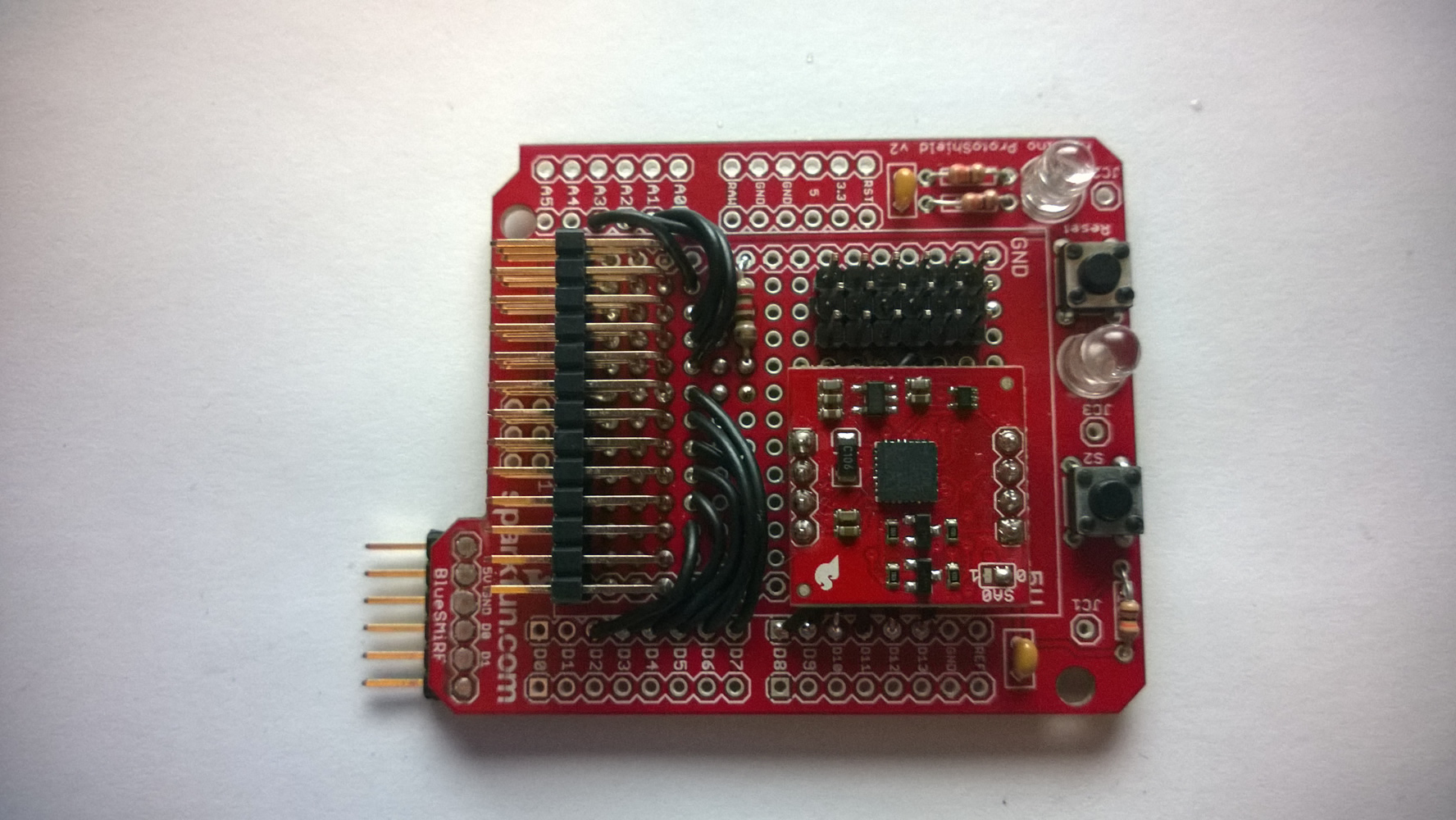
Fig 4: The ServoBot Board with the LSM303 in place
Whilst it is true that I could have easily accounted for the orientation etc via software implementation, I instead opted to instead break out the I2C (A4, A5) pins so that I can connect to an externally mounted LSM303. My current plan is to use the original mounting hole made in the body for the Power Disributor Board to mount an LSM303 which would not only be central to the robot but also enable the correct default orientation.
Video 1: The completed board & power harness in action
The above video (Video 1) shows the completed board wired up to the power harness and a couple of servos. With the board complete I am now well on the way to completing my robot Ratchet. Over the weekend I am planning to implement the external LSM303 mounting and create a couple of servo plug connections for two Sharp IR sensors and also a couple of LED’s.
Once this is done I can begin on Ratchets final assemble.
For my other ServoBot Clank, I am thinking of doing another revision of the board. I may even go as far as producing my on PCB. This would enable me with more room to add numerous additional capabilities such as 3v3 regulation and making the voltage divider resistors optional, however only time will tell.