Kinect Robot Power Adapter
Those of you who have been following via my facebook page would have seen that I have been toying around with the idea of utilising the power of the Kinect with my latest robot build, Koothrappali. In order to facilitate this however I first had to verify that I could run the system unmodified with my tablet and with a portable power source.
Point one was easy to resolve, and after installing the drivers I soon had the Kinect up and running. Point 2 however, was a little more tricky, but also achievable via the development of a custom Kinect Robot Power Adapter.
Build Your Own Adapter
In this post I will detail the steps I followed to create the adapter so that you too can add Kinect functionality to your robot or make use of your 360 Kinect with your PC without having to fork out £30+ on an equivalent PC adapter.
Why I Did It Like This
Whilst it is true that in reality I could have achieved the same outcomes via a little modification to the supplied Kinect cables. I also use the Kinect with my 360. Because of this factor I set myself an additional requirement, that no modification to the hardware was allowed. This meant that no wires could be cut and that the casing etc must all remain intact. If you too are worried about these issues then this is the adapter guide for you!
Investigation Of The Hardware
I decided early on that the best solution would be to fashion my own connector. This means that whenever I want to use the device for Koothrappali, all I need do is unhook it from its DC/USB adapter and plug it in. Careful examination of the Kinects bespoke adapter revealed that it be based on a standard USB type connection, however with a few major differences:
- Its double sided
- There are 5 pins on the second side instead of 4
- The connections are slightly offset to the side.
The spacing between pins however was an exact match. With this in mind I concluded that I could approach the build in two ways: fashion a custom jack out of USB connectors or etch my own. Rather than invest time and resource (just in case the overarching concept was not feasible, also I hate chemicals and avoid whenever possible) I opted for option one.
Creating The Connector Heads
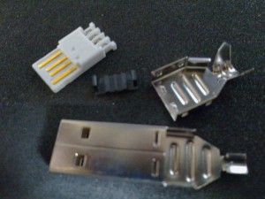
In order to build the heads I used three standard USB A plugs. First I separated the main connector boards. The board it the white block with the connectors attached as shown in the image to the left. You will also need to keep the little black wire keepers to hand, however the rest of unit can be put to one side and/or thrown away.
Fig 1: USB A Plug
With the parts now ready I started on the 4pin head. If you line one of the boards connectors up with the Kinect sockets 4 pin side you will see that it almost fits perfectly however with a slight offset.
In order to fix this I cut away about 1/2mm from the respective side so that when inserted face to face the connections would line up. Next I sanded down the plastic lip surrounding the boards edge so that the contacts were proud.
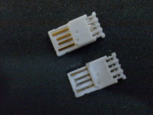
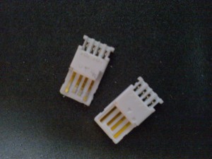
With this achieved the 4 pin head was complete. The following image (left) shows the head before and after (lower) modification. Note the section cut away on the second board from top left through to the middle.
In order to fashion the 5 pin head (below: right, left) I had to cut away a section so that I could mount a new connector to the board. The new connector was removed from the as yet unused 3rd plug. This is done simply with a Stanley knife and a bit of care. As you can see in the image the cut away section is flush with the other connectors and reaches back into the middle of the body of the board. In my build I followed the line from edge of the adjacent connectors edge.
[column span=”2″]
Fig 2: USB A Before (left)
[/column]
[column span=”2″]
Fig 3: USB A After (right)
[/column]
I then took the connector removed from the 3rd plug and super-glued it to the plug, ensuring a separation of about 1/2mm from the adjacent connector. The connector also needed bending twice at 90 degrees so that followed the edge of the casing (see wiring diagram below). Finally as with the 4 pin head, I sanded the surrounding rim so that the connectors are proud. With this achieved the 5 pin head was also complete.
Wiring The Heads
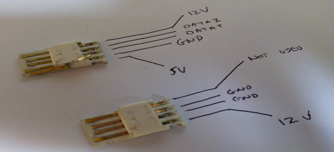
Next I had to work out the lines for each connection. This was done with a little play and a little googling for verification. The following image details the lines for each of the connectors. The line reading data Z should read data minus (my pen slipped, honest).
Fig 4: Wiring Diagram
Please note that with the exception of the additional connection that the 5 pin head lines are equivalent to that of a standard USB connection. This factor formulated the basis of my wiring. I started the process by cutting a USB A cable in half and identifying the lines as follows (luckily I used a standard typical cable):
Red – 5Vcc
Black – Gnd
Green – Data z
White – Data +
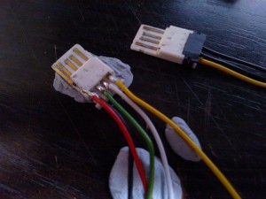
Next I moved onto soldering lengths of wire to the heads. For simplicity I used equivalent colors for the known USB and GND lines and added Yellow for the 12V lines. At this stage I also twisted the GND’s together and the 12V lines together so that they in effect became 1 GND and 1 12V line.
I next began to fix the heads together. Be aware you will need to do a little sanding to the underside of each of the heads to ensure that they fit snugly into the Kinects adapter socket. Once I was happy with the fit I glued the heads together with superglue ensuring that they were lined up correctly to marry with the socket connectors upon insertion. At the same time I also fitted the two black cable keepers kept from earlier.
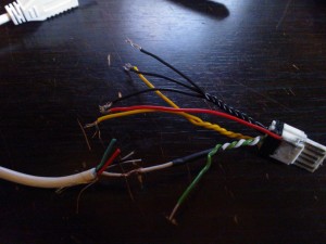
I then began to splice the wires to those of the usb cable.
[column span=”2″]
Fig 5: Soldering Of The Heads
[/column]
[column span=”2″]
Fig 6: Splice of Wires
[/column]
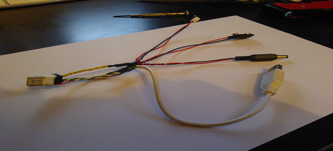
Finally I also spliced 3 power connectors, a JST, PP3 and 2.5mm Jack to the GND and 12V lines. These provide the connection to your designated external power-source. In reality you will only need one but I thought I’d cover all bases and potential usage in a variety of contexts.
Before soldering and shrink insulating the connections I ran a few tests to ensure that everything was working. If you are having issues at this stage try checking your connections and ensure that your data +/- are the right way round (be careful as this could damage your PC and/or Kinect).
Once everything was working happily I then soldered and insulated the cables using cable shrink wrapping. The following images shows the fully soldered adapter cable.
Fig 7: Spliced and Shrunk Wrapped
Finally I wrapped the exposed cables with insulating tape and the adapter was completed (see top of post for image). As always Ill finish up with a quick video, this time demonstrating the adapter in action. An interesting outcome I noted during testing with my power-pack is that it seems that you can power the Kinect off only 8.5V.
The video demos this working for both camera streams and the motor (try at your own risk).
That’s it for this post, I hope you will find it useful. Currently I am working on a 11.1V power-pack for the Koothrappali build that will utilise this adapter via the JST connection. More information on this shortly. For preview postings and to find out what I’m at don’t forget to check out my facebook page.
